Jun 1, 2023
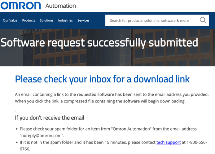
How To Download Omron CX Programmer (CX-One) for Free
Dec 14, 2018
How to Change Servo Drive Parameter using Omron CX Drive
In industrial automation, we install and program many servo motors and drive in industries every day and so sometimes it becomes very problematic to set each and every drive with the display panel. So to make this an easy process, you can also use servo drive software to make changes or set new parameters through your laptops. Today let me tell you about CX drive, which is Omron product and by which you can program your drive without touching display panel. Almost all the automation product manufacturing company provide servo drive software so you can check with your drive provider. Subscribe to Automation-Talk by Email.
Required Conditions
1. You must have CX-Drive installed on your laptops/desktops.
2. Servo drive should be connected to set or change parameter's online.
In this example we have selected R88D servo drive.
Recommended Reading: How to Reduce Electro-Magnetic Interference in Servo Drives
Steps to Change Servo Drive Parameter Using Omron CX Drive
1. Start CX Drive software in your laptop. If you have installed CX-One software and all its component, then it will be under Omron -- CX-One -- CX-Drive
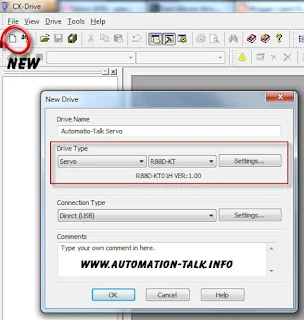
2. Now click on new and make your servo drive project. Here you will have to select a servo drive model from the list and you can also set the maximum rating of the drive through settings.
3. Now expand your new project and click on Parameter Editor. In parameter editor, you can even choose from different parameter list like basic parameters, gain parameters, vibration suppression parameter, analog control, special setting parameter etc.
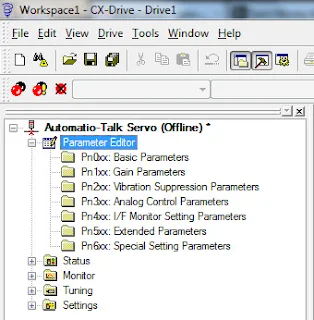
4. Suppose we first want to set basic parameters, then just click on it and you will be shown all the basic parameters of the servo drive.
Now suppose we want to change control mode of the drive, then we can use parameter Pn001 and can set its value as required for the project. See the example below.

Similarly, you can change any parameter of servo easily.
Now to transfer this new setting to your drive, just go to transfer, which is under drive tab and transfer the settings to your drive. And if you are not connected to your drive you can also save your setting for after use. I like this method because you can use the same settings for every drive and you can save your project parameter wise, which saves your precious time.
If you like our articles, please consider them sharing with your friends and do like us on Facebook. You can also share your views and feedback through comments.
Jun 18, 2018
PLC Programming for Tank Level Measurement using Ultrasonic Sensor
In our earlier post, we saw the PLC Logic for Auto Filling of Tank using digital inputs for LOW and HIGH-Level signals.
PLC Programming for Tank Level Measurement Using Ultrasonic Sensor
First of all, we need to choose the Ultrasonic/Capacitive level sensor according to our tank level height. The sensor will give a 4-20mA signal to PLC and accordingly, we will calculate the level in the tank.
PLC Logic Development:-
Now, we need to connect the analog input from the ultrasonic sensor to PLC, we have already told that in our earlier post. You can see it here.
After that, we have to write SCL (scaling instruction) in the PLC to convert the value received by PLC to the scale we want.
So that when the Ultrasonic sensor will give 4mA signal then the level in the tank will be zero and when a signal of 20mA will be received then the level in the tank will be 5000cm.
In SCL instruction, we have to define the scaling parameters in some D:-
D200 - 0
D201 - 0
D202 -5000 (hexa)
D203- 0FA0 (hexa)
Here the value 0 to 0FA0 received by PLC will be scaled to 0 to 5000 (our tank height).
Now in this PLC Program we have kept the low level at 2500cm and the high level at 4600cm. You can download the PLC program from below, we have built the PLC Program using the Omron CX-supervisor software. Both the .cxp and .pdf files are included.
Download PLC program for Tank Level Measurement.
Hope you like this PLC program on controlling your Tank according to the measurement using an Ultrasonic sensor. If you face any problem with this PLC Program or want any modification then write us in the comment section.
Mar 4, 2018
Conzerv Energy Meter EM6436 Modbus Communication and Connection Diagram
Conzerv has a range of EM series Energy meter and there are various different models available for your different need and according to the application. Conzerv Energy meter comes with and without Modbus communication feature, so be sure when selecting Energy Meter according to the application. If you want to communicate it with PLC then make sure that it is MODBUS Enabled.
The EM series Power meters offer complete load management facilities in a compact package. If you like to see more such posts, please subscribe to Automation-Talk by Email.
How to check whether Conzerv Energy meter is MODBUS enabled?
1) First of all, check that terminals 7 and 14 of meter does not have black dot mark, if there is a black dot market on it then it is not MODBUS enabled.
2) Secondly, check that on the front left bottom side RS485 is written and the color of the dot before this, if the color of the dot is white then it is MODBUS enabled and if it is black then it is not MODBUS enabled.
All Conzerv Energy and power meter come with different function keys in the front side for easy set up of the parameters and also some models have TURBO key through which you can directly go to set up mode.
Connection Diagram of Conzerv EM series Energy Meter
NOTE:- Click on the picture for a clear view.
In the above picture, you can see the connection of energy meter. Connect your meter accordingly. The meter has 3 line display and display the parameters sequentially one by one i.e their name and value one by one.
Now the main question is how to communicate Conzerv Energy Meter in MODBUS?
So here is the answer, first of all, make proper hardware connection of MODBUS accordingly that is connect positive of PLC RS485 port with terminal 7 and negative of PLC RS485 port with terminal 14 of Conzerv Energy meter.
Now you have to make PLC program accordingly, generally, in MODBUS we read the parameters like a line to line voltage, frequency, current, power factor etc. Each parameter has its unique address in the energy meter and it has to be read through the query in MODBUS.
Make sure to set the node id, baud rate, parity in yours Conzerv energy meter properly using the setup mode.
You can download the address map of Conzerv Energy meter EM series from here .
Click here to download.
Now the question is How to read data from Conzerv Energy meter in MODBUS using OMRON PLC.
You can review the Omron PLC MODBUS communication from here.
So here is the Data format to read:- 01 03 04 (address - 1) 02
Make sure to subtract 40001 from the address.
Response from energy meter:- 01 03 00 05 0486 9042 4800
Here the value of the parameter in response is 4248, remember that the response of Conzerv Energy meter is always in float, so make sure to convert it accordingly. For example in the above response, the value returned by EM is 4248 in float which is equal to 49.98 in decimal and it is the value of frequency.
So accordingly you can read others parameter too by using the above query format. Hope you like this article and if you do, do not forget to subscribe to Automation-Talk by Email.
Oct 9, 2017
PID Control with Auto Tuning in Omron PLC
PID control as we all know is a fundamental thing used in process automation. For PID control we generally use PID Controller, but in Omron PLC there is one exclusive instruction for PID purpose. This instruction is very helpful in many application where we can minimize cost by using software PID inside PLC. In this post, we will see that how to use this PID Instruction in Omron PLC.
PID Control Feature In Omron PLC
Omron PLA is very popular in the Automation industry and used in a wide range of applications. Omron PLC have exclusive feature that we can create a PID inside PLC by using an PLC Instruction. The name of PLC instruction is PIDAT.
Syntax:- PIDAT S C D
Where S is the Input word, C is the control/Parameter Word and D is the first output word.
When the input condition of this instruction is on then it performs the PID control on the bit in word S according to the control word C. The different bits of Control word C defines the PID process parameters. Let us see the meaning of each bit of control word C. The word C defines the target value of the process being controlled.
C+1 defines the proportional band i.e the parameter for P action expressing the proportional control range/total control range. C + 2 defines Tik Integral Constant, a constant expressing the strength of the integral action. As this value increases, the integral strength decreases. C+3 stands for Tdk Derivative Constant, constant expressing the strength of the derivative action. As this value increases, the derivative strength decreases. C+4 stands for the sampling period, the sampling period can be designated in units of 10 ms (0.01 to 99.99 s), but the actual PID action is determined by a combination of the sampling period and the time of PID instruction execution (with each cycle).
Below is the diagram explaining PID action.

PID action combines proportional action (P), integral action (I), and derivative action (D). It produces superior control results even for control objects with dead time. It employs proportional action to provide smooth control without hunting, integral action to automatically correct any offset, and derivative action to speed up the response to disturbances.
This instruction is very useful for PID block creation. Dont forget to subscribe to get all latest updates. Subscribe to Automation-Talk by Email.
Apr 29, 2017
How To Set & Release Omron PLC Password
Every PLC has a feature to lock the program and Data Words inside the PLC, so that no one else can see and copy the program made by you. We do a hard job to make PLC Programs and thus also wants that no one else should take the credit of our hard work. In this article we will see "how to set and release the password in Omron PLC".
How to Put Password in Omron PLC
To set the password in Omron PLC like CPM2A, CP1E, CP1H etc., first make your program and after that in the left hand side project workspace is there. Right click on the PLC name and select Properties and Under protection tab you can set the PLC Password.
See below picture for a better Understanding.

You can also Release the Password.
To release the password just Select PLC tab -- Protection and then click on Release password. Once you have set the password in Omron PLC for Program and memory data then no one can Upload the PLC program without knowing the password. Also, the password will always be saved in the program and you can see it if you forgot what password you have put.
Also check out the Step by step procedure for removing PLC Password.
Don't forget to subscribe to get all PLC, HMI and SCADA updates in yours Inbox.
Feb 26, 2017
Increasing/Decreasing Speed using Buttons in JX Drive
In some of the application in industries, need of increasing and decreasing the speed using VFD drive through a single control panel using the push of Buttons is required. One of the best example of such machine is sheet laminating machine where operator can simply increase/decrease the speed using buttons. In Omron JX drive this function can be performed with ease through parameter of the drive. Here we are not talking of MODBUS communication and will use input from terminal. This feature can also be done using MODBUS communication and also with the help of POT. Subscribe to Automation-Talk by Email.

Below are the important parameters which need to be set in Omron JX drive to use increasing and decreasing Speed feature using Buttons.
1. A001: Frequency reference selection:
In this parameter select 02 to use Digital operator as the input source for frequency. By default this is set to 00 (Digital Operator- Freq. Adjuster).
2. A002: Run Command Selection:
By default this is set to 02 for digital operator. Select 01 for terminal mode. By selecting this parameter, you will only able to give run command through control panel or terminal buttons.
3. C001: Multi-function input 1 selection: UP
This is the parameter which lets you use first input button, say Start button as increase button. By default this parameter value is set to 00 for Forward (FW). Change this value to 27 which will increase the frequency.
4. C002: Multi-function input 2 selection: DOWN
By default this parameter is set to 01 for reverse (REV) and we have to select 28 which will decrease the frequency. This feature is applicable while the machine is in RUN mode.
Notes the below points while using C001 and C002 parameters:
1. While the UP/DWN terminal is turned on, the acceleration/deceleration time depends on F002, F003/F202, and F203.
2. You can store a frequency set value after UP/DWN adjustment. Choose whether to store the value with C101.
3. Also, you can clear the stored frequency set value by allocating 29 (UDC) to the desired multifunction input and turning on/off the UDC terminal.
4. The UP/DOWN function is disabled when the JG operation is enabled.
5. The UP/DOWN function is enabled when the frequency reference selection (A001) is set to the Digital Operator (02).
6. The UP/DOWN function is enabled when the multi-step speed reference is enabled.
After setting the above parameter you can test this by using Start and Stop buttons. Use start button for increase and stop button for decrease. Now press and hold the increase button to increase the speed and release the button to hold the speed to that point and do same for decreasing the speed. If you have any issue in setting your button to UP and down mode (increase/decrease) then please let us know. To get the latest tutorial and program subscribe to Automation-Talk by Email.
Nov 7, 2016
PLC Programming For Counting Encoder Pulses
 Encoder is mainly used for feedback purpose to know the position and distance measurement in Industrial applications. But before going in to the PLC Programming we should be familiar with Types of Encoder , Interfacing of Encoder with PLC.
PLC Programming For Counting Encoder Pulses / Feedback:-
Actually encoder is mounted on the shaft whose position we want to determine or want to monitor its value. Encoder have some PPR and they gives accordingly that number of pulses in one revolution.
Note:- The coupling of encoder with shaft should be done properly for accurate measurement otherwise the efficiency will decrease or it can even destroy.
PLC Logic Development:-
Now we will see the step by step detail for making the PLC Program. First of all we have to decide the condition that when should the counting start i.e when the pulses given by Encoder will be counted. Generally we want this at the auto-cycle start , So here we are considering at Auto Bit ok condition , however it can be done as per application requirement.
We here are considering the example of Omron PLC CP1H, in every PLC there is a Instruction for counting the high speed pules, In Omron it is PRV , so we will write PRV Instruction.
In PRV we have to define the port number where we have connected the Encoder and control Data. After that the value(encoder pulse value) will coming in one Data Register of PLC.
Now we have to decide as what to do this value. Let us take one example , suppose our encoder is of 360PPR i.e it will give 360 pulses in one revolution, Encoder is connected to motor shaft which is driving a conveyor and after every ever 300mm conveyor will stop and a cylinder will come down to cut.
So first we will calculate that in 1 revolution of encoder how much the conveyor moves.
If in 360 pulses conveyor moves 100 mm then we find that , for 1080 pulses of encoder conveyor moves 300mm.
Note:- Settings in the CX-Programmer.
So, after every 1080 pulses we will stop the motor and on the cylinder output and simultaneously reset the Encoder value, and continue this process. We will compare the Encoder Pulse value with the 1080 and at when they equal, motor stops, cylinder down and encoder value reset and motor again runs.
We have made the PLC Program accordingly. See the PLC Program below, we have included both the .cxp and .pdf files.
Download the PLC Program.
Also if you face any problem then you can leave us a comment. You can subscribe to get all related PLC Programs, SCADA Tutorials, HMI, VFD Installation related articles in yours inbox. Subscribe to Automation-Talk by Email for more such articles.
Jul 24, 2015
Panasonic FPΣ Series PLC & NV HMI Communication
As discussed in the previous article the Panasonic FP-X series and NV HMI RS232/RS485 Communication, here will see the communication of one more PLC by Panasonic i.e FPΣ Series PLC with NV HMI. NV HMI can be connected either at Tool port or the COM port at the PLC, and communication can be done through RS232 or RS485.
NV HMI Communication with Panasonic FPΣ Series PLC & NV HMI Communication
We will see the complete step by step procedure for the communication scheme between Omron NV HMI and Panasonic FPΣ-series PLC. First of all, lets us see how we will connect the NV HMI with FPΣ-series Tool Port.
||Panasonic FPΣ-series PLC Tool Port Connection with NV HMI[RS232]||
For making connections via Tool port we need a Mini DIN 5-pin connector. Just make the connections as shown below.
PLC Tool Port>--------------------------------------------------NV HMI
PIN 1 (SG)-------------------------------------------------------------Terminal 8 (SG)
PIN 2 (SD)-------------------------------------------------------------Terminal 5 (RD)
PIN 3 (RD)-------------------------------------------------------------Terminal 4 (SD)
Connecting to an FPΣ-series COM Port[Rs232]:-
PLC COM 1 ----------------------------------------------------------- NV HMI
PIN SD--------------------------------------------------------------------Terminal 5(RD)
PIN RD--------------------------------------------------------------------Terminal 4(SD)
PIN SD--------------------------------------------------------------------Terminal 8(SG)
Note:- Also short the RS and CS at the PLC side. Connect the RS and CS terminals on the COM1.
Connection Diagram for FPΣ COM Port 3 (RS-485, 1 Channel):-
PLC COM 3-----------------------------------------------------------------NV HMI
PIN + ------------------------------------------------------------------Terminal 4 (+SD)
PIN - ------------------------------------------------------------------Terminal 5 (-SD)
NOTE:- Short the Terminal 4 with 6 and Terminal 7 with 8. Turn ON pins 1 to 4 on the switch on the back of the COM3.
Also make the following Communications Format Setting for the RS485 Communication.
COM port 1------------>>> unit number 1
COM port 1------------>>> communications mode Computer link
COM port 1------------>>>transmission format 8 bits, odd parity, 1 stop bit, terminal
CR (fixed), no STX
COM port 1 baud rate setting ------------>>>38,400, 57,600, or 115,200 bps
Now after making the Hardware connections as desired per the application, we now just have to define some communication parameters at both the HMI and PLC side.
Open the NV designer (NV designer is the HMI software) and create a new project and he PLC type select as "Panasonic FP Series." After this got to PT-------NV Configuration and make Baud Rate as 19200 Kbps, Data Bit as 8, Stop Bit 1 and Parity as Odd.
Now we are done with all the necessary settings to be done for the communication between NV HMI and Panasonic FPΣ Series PLC. If you face any problems then you can write us in the comment section. Also, you can subscribe to get all latest updates in your Inbox. Subscribe to Automation-Talk by Email.
May 24, 2015
PLC Logic Auto-Filling Tank - Free PLC Programming
 Almost in all of the industries Tanks are there for storing up the liquid,chemicals or there are overhead water tank for the water supply in plant.Generally for overhead tank a pump is there for filling of the tank or in other cases also there is a motor/pump for filling purpose of tank. So if the filling of tank is a manual process then a operator has to be employed for the ON and OFF process of the PUMP.
PLC Logic for Auto-Filling of Tank - Free PLC Programming
So, as told above if the process of filling is manual then we have to assign this task to a operator to ON the pump when the Tank empties and OFF the pump when the Tank fills. But in today's scenario all the process are automatic. So today we will discuss the automatic filling of tank and automatic ON-OFF of pump according to tank level. We will build a PLC Logic for this complete application. To write the PLC Program for this process we should understand the logic first.
The PLC Logic will be like following
To monitor the level in tank we can either use a Ultrasonic/Capacitive level sensor which will give analog input to PLC OR we can just put two sensor one at HIGH level and another at LOW level and they will give the signal to PLC for HIGH and LOW level respectively.
When the level will be LOW in tank then the PUMP will start and the filling of tank will start and when the level reaches the HIGH level the PLC will receive the HIGH level signal and the PUMP will stop, so the filling of tank will stop. When again tank empties the PUMP will start on its own and the process continues.
Generally the On and OFF of pump at two levels is a task that requires little intelligence. Suppose the height of tank is 5000cm then the low level should be around 2000cm and high level at 4600 cm. It is done because if for example the low level is set at 300cm hen the PUMP will start at 300 cm and suppose if at the same time the consumption rate increases than the supply of PUMP then the tank will empty. So keep in mind this thing while setting the LOW and HIGH level in Tank.
Well there is no need to install a separate PLC for this small application, as almost all the major industries have the PLC installed so the logic can be built in that existing PLC and thus there will be savings.
PLC Logic Development
Here we will take example of Omron PLC and build the PLC logic using CX-Programmer.
INPUTS :-
0.0-------------------------------------------------------------- Low level Signal
0.1-------------------------------------------------------------- High Level Signal
OUTPUTS:-
100.0 ------------------------------------------------------------ PUMP ON
Here we have build the PLC Programming using the digital Inputs, but the same can using the Ultrasonic/Capacitive Level sensor and taking the Analog input to PLC. You can download the PLC program from Below.
Download PLC Programming logic of Auto Filling Tank.
We have attached both .pdf and .cxp files so that who don't have CX-Programmer software can still view the logic and understand the PLC Logic.
We will also build the PLC logic using the Analog input to PLC, so keep visiting and you can subscribe to Automation Talk for such more PLC Programming examples, SCADA tutorials, VFD applications and HMI Programming.
If you have any doubts regarding this PLC Program then you can write in the comment section below and we will get back to you ASAP. Don't forget to Subscribe to Automation-Talk by Email.
May 9, 2015
Using PLC Clock Time in Omron PLC Programming
Almost every plc have the clock function that is we can get the time value in the plc data words. We can synchronize the plc time with the system time at the time of program downloading. PLC stores the value of time , day , Month and year in its internal data words. We already have discussed about the plc internal words.
Reading the Year/Month/Day/Time Value in PLC :-
Many a times while developing the plc logic sometimes it is required to use the time in program to perform a particular function. Also there must be situation when we need to operate a particular device on a Specific date and time. So all these things are possible in PLC , all we need is to find out the plc system words where these values are stored.
Here we will see the example of Omron PLC. One thing we should keep in mind is that the plc must have battery installed so that real time monitoring of Date and Time is possible. In omron PLC there are 4 system words for storing the value of Year,Month,Date,hour,minute and second.
A351 to A354 are the system words in Omron PLC which stores these values. See below for the complete detail.
A351.00 to A351.07 Seconds: 00 to 59
A351.08 to A351.15 Minutes: 00 to 59
A352.00 to A352.07 Hour: 00 to 23
A352.08 to A352.15 Day of the month
A353.00 to A353.07 Month: 01 to 12
A353.08 to A353.15 Year: 00 to 99
A354.00 to A354.07 Day of the week
00: Sunday, 01: Monday, 02: Tuesday, 03: Wednesday 04: Thursday, 05: Friday, 06: Saturday
So by seeing the above values in these system words we can get the exact Date and Time. We can compare the values in these words with our pre-defined DM words and make the plc logic accordingly. Also when we download the program in plc then for the first time we have to synchronize the plc clock with our system clock. See below picture.

Now for example take a situation that we need to operate a particular output to be on 8 pm 20 Dec 2012 and be on afterward. So for this we will use compare instruction and compare the A351 with #0 and A352 with #2020 and A353 with #1212 and when these conditions gets satisfies the output will be on. If you see properly then these condition will be satisfied exactly on 8 pm 20 Dec 2012.
We hope that this plc tutorial will help you to use the plc clock time in developing plc logic . If you still face any problem you can write us in comment section. Also you can subscribe to get all latest updates in plc programming.Subscribe to Automation-Talk by Email.
Apr 18, 2015
Omron HMI Communication With Keyence FA-M3 Series PLC
NV Range of HMI by Omron is capable of communicating with a wide range of PLC. As we already discussed the NV HMI Communication Cable for Panasonic PLC ,Omron HMI Cable Diagram for Allen Bradley PLC , Omron NV HMI Connection with Siemens PLC. Today we will see the step by step procedure for NV HMI Communication with Keyence FA-M3 Series PLC.
RS 232 Communication Between Keyence PLC and Omron NV HMI :-
There are to methods for making a physical connection between HMI & PLC. Either we can connect through Personal Computer Link Module OR Direct Connection to CPU Module. We will see the communication cable diagram for both the types of connections.
||Connecting through a Personal Computer Link Module||
For making this type of connection you need to have the Link Module F3LC11-1N or F3LC11-1F or F3LC12-1F. Make the cable with the following connection diagram.
PLC Side ----------------------------------------------------------------------HMI
Pin 2(RD) -----------------------------------------------------------------Terminal 4(SD)
Pin 3(SD) -----------------------------------------------------------------Terminal 5(RD)
Pin 5(SG) -----------------------------------------------------------------Terminal 8(SG)
Note:- Also short the Pin 4 and 6 , Pin 7 and 8 at the PLC Side.
||Direct Connection to CPU Module||
For this type of communication scheme you will need the KM11-2T Programming Tool Cable. Make the connections as shown below.
PLC Side ----------------------------------------------------------------------HMI
Pin 2(RD) -----------------------------------------------------------------Terminal 5(SD)
Pin 3(SD) -----------------------------------------------------------------Terminal 4(RD)
Pin 5(SG) -----------------------------------------------------------------Terminal 8(SG)
Note:- Also short the Pin 4 and 6 , Pin 7 and 8 at the PLC Side.
Now after making the hardware connection as per your suitability , we have to make some settings both at PLC and HMI side.
|| Settings in NV Designer for Keyence Plc||
NV Designer is the HMI software used to make the screens in NV HMI. Open the NV designer software , Create a New Project and select the proper NV HMI Model which you are using and after that in PLC Type select "Yokogawa FM-M3 Series" and then click Next and select System Memory Area accordingly.
Now we have to define Communication Parameters Both at HMI and PLC side. To set the Communication Parameters in the NV Designer go to PT----NV Configuration and under Communication Parameter Tab select baud Rate as 19200Kbps , Data Bit as 8 , Stop Bit 1 and Parity as None and check sum Enabled.
Also make the following settings in Keyence FA-M3 series PLC:-
Station number--------->> 1
Baud rate--------->> 19,200 bps
Data bits--------->> 8
Stop bits--------->> 1
Parity--------->> None
Checksum--------->> None
End character specification--------->>Enabled
Protection--------->> None
After doing the step by step procedure as told above , you can communicate the NV HMI with keyence PLC easily . Make a sample screen in NV HMI , and test the communication. If you still face any problem then you can write us in comment section. Also you can subscribe to get all latest updates regarding PLC & HMI by subscribing to Automation-Talk by Email.
Mar 1, 2015
PLC Programming for Dancing Light - PLC Programming
Many users mailed us for making the PLC program for the dancing light, so here we will see the PLC Logic for making a fancy light decoration system.
PLC Programming for Dancing Light - PLC Programming
Here in this PLC Program, we are considering six numbers of LEDs, 1 start push button, 1 stop push button, and 1 selector switch. We will write the PLC program for 2 different modes i.e the LEDs will glow in two different patterns.
Recommended Article: Free PLC Software's for Ladder Logic Programming
Mode 1 Pattern of LED Glowing:- While writing this PLC logic we have made the PLC program in such a way that when we will push the Start button then LED 1 will glow after 1 second LED 2 will glow and again after 1 second LED 3 will glow and so ON and after 6th LED the cycle will start again. The number of LED's can be more as per the need and application.
See the Below table for a better understanding.
Time -----------LED1 ------------LED2---------LED3---------LED4--------LED5------------LED6
T=0sec ---------OFF--------------OFF----------OFF----------OFF----------OFF-------------OFF
T=1sec ---------ON --------------OFF----------OFF----------OFF---------OFF-------------OFF
T=2sec ---------ON --------------ON-----------OFF-----------OFF---------OFF-------------OFF
T=3sec ---------ON --------------ON-----------ON------------OFF---------OFF-------------OFF
T=4sec ---------ON --------------ON-----------ON------------ON----------OFF-------------OFF
T=5sec ---------ON --------------ON-----------ON------------ON----------ON--------------OFF
T=5sec ---------ON --------------ON-----------ON------------ON----------ON--------------ON
and then again the cycle resets after every 6 seconds.
Mode 2 Pattern of LED Glowing :-
In the second mode , which will be on when we will select it by selector switch the LED 1 and LED6 will glow first for 1 second then LED 2 and LED 5 will glow and then LED 3 and LED 4 .
See below table for a clear understanding.
Time -----------LED1 ------------LED2---------LED3---------LED4--------LED5------------LED6
T=0sec ---------OFF--------------OFF----------OFF----------OFF----------OFF-------------OFF
T=1sec ---------ON --------------OFF----------OFF----------OFF----------OFF--------------ON
T=2sec ---------ON --------------ON-----------OFF----------OFF----------ON---------------ON
T=3sec ---------ON --------------ON-----------ON------------ON----------ON---------------ON
And then after 3 seconds the cycle resets.
PLC Logic Development for Dancing Light
INPUTS
0.0 --- Start Push Button -- (NO)
0.1 --- Stop Push Button --- (NC)
0.2 --- Selector Switch --- (1 pole)
OUTPUTS
100.0 ------------- LED 1
100.1 ------------- LED 2
100.2 ------------- LED 3
100.3 ------------- LED 4
100.4 ------------- LED 5
100.5 ------------- LED 6
We have considered only 6 LED here only, however, the PLC Programming can be extended for any number of LED you want, and also the glowing pattern can be changed as you like.
You can download the PLC Program below. We have attached both .pdf and cx-programmer files.
Download PLC Program for Dancing Light.
If you have any queries in PLC Programming, then write in the comment section, or want any PLC program related to Dancing Light then tell us we will make it for you.
Also, you can subscribe to Automation Talk to receive the latest updates for PLC Programming, SCADA Tutorials, HMI Programming, MODBUS and AC Motors.
Jan 28, 2015
How to Connect Omron Rotary Encoder to PLC
Omron Rotary encoder E6B2 comes with open collector output and as well as line driver output. It has external shaft dia up to 40mm and it has a resolution of up to 2000PPR.
Some may want to know what is PPR in encoders ?? well PPR stands for Pulse Per Revolution i.e the number of pulses it will be giving in one full revolution.Also as per our need we can select either PNP or NPN type output. Generally in all the cases we need to interface the encoder with PLC to receive the PULSES.
The use of encoders in Automation is for detecting/calculating the length or distance traveled with the input from encoder pulses , for measuring the speed or for high-processing of data. For more detail on encoders you can see here.
How to Connect Encoder to PLC?
For connecting the Encoder to our PLC we have to make sure that our PLC accepts high speed counter inputs and we have to connect the encoder accordingly to that terminals only. Omron PLC CP1E/CP1H have 4 high speed counter inputs and we can connect up to 4/6 encoders.
Omron encoder E6B2 series have 5 wires and of different colour. Make connections as depicted below.
Brown------------------------------------------------------------------- + 24 V DC
Blue ------------------------------------------------------------------- 0 V Dc
Black ------------------------------------------------------------------ Output Phase A
White ------------------------------------------------------------------ Ouput Phase B
Orange ----------------------------------------------------------------- Phase Z
So connect your Encoder accordingly as shown above. Here we will tell you how to interface it with PLC. We will take example of OMRON PLC CP1E. We have to just connect 3 wires to PLC high speed counter Terminals and configure them in the software for Receiving the Pulses.
Interfacing the Encoder with Omron PLC CP1E:-
We will take example here as connecting the encoder to High speed counter 0.
Black-------------------------------------------------------------- 0.0
White-------------------------------------------------------------- 0.1
Orange------------------------------------------------------------- 0.4
Similarly we can connect it to any high speed counter input , just we have to check what are the terminals assigned for that HIGH Speed Counter in PLC.
After making the connections we have to write the suitable PLC Program for the reading of Pulses and processing the PV value of Encoder.
PLC Programming and necessary settings in CX-Programmer will be discussed in next post. So just reading here and also you can subscribe to get all related updates in yours Inbox. If you are facing any problem in connecting up your encoder then feel free to write in comment sections. PLC Programming for Encoder will be discussed in next post. If you like our articles do Subscribe to Automation-Talk by Email for more such awesome articles.
Jan 20, 2015
Download OMNUC U-series Computer Monitor Software
There are many useful software which Omron offers for free and one of such software for servo is OMNUC U-series. It is Computer Monitor Software which is used for many useful functions and can be used for Parameter editing, Jog operation and auto tuning, checking the condition of servo drivers, displaying graphs related to speed or torque on a IBM PC/AT or compatible computers. Subscribe to Automation-Talk by Email.
This is useful software for many servo drives and as stated above can be used for various operations. The main servo supported by this software are as below.
I. R88D-UA**H/-UA**L (30 to 750 W, analog input)
II. R88D-UP**H/-UP**L (30 to 750 W, pulse-train input)
III. R88D-UA**HA/-UA**LA (30 to 750 W, analog input, upgraded version)
IV. R88D-UP**HA/-UP**LA (30 to 750 W, pulse-train input, upgraded version)
V. R88D-UT**H (1 to 5 kW, combined analog/pulse train input )
VI. R88D-UT**V/-UT**W (30 to 750 W, combined analog/pulse train input, product meets EN standards)
VII. R88D-UEP**H/-UEP**L (100 to 750 W, pulse-train input, UE models)
This is very versatile software and enables communication with up to 14 Servo Drivers using only one computer and also supports absolute encoder (HA/LA) setup.
How to Get OMNUC U-series Computer Monitor Software for FREE
1. You will first need to go to myomron.com.
2. Register yourself, as you will need it to download the OMNUC U-series software.
3. Now go to Download section and then to Products.
4. In product click on Software and then to Umon.
5. There you can see the download link of the OMNUC U-series software, its manual and connecting cables diagram.
6. OMNUC U-series is a small program and is only 201.13kB and it is a very old program and I don't think many of you may be using it.
Complete path can be summarized as /downloads/4.Products/Software/Umon/
Note: Do read the installation notes before installing the software on manual.
Do let us know if you already using this software and also let us know how it is useful to you. Please also provide feedback about this software. Do subscribe to our blog for more such free Automation software's.
Aug 11, 2013
How to Select Servo Motor for Projects using Free Tool
In industrial automation, proper selection of automation products is very important whether it is a PLC, sensor, motor, servo or any other component small or big., every one play a vital role. Improper selection of these component may lead to complete failure of the project. Therefore in this tutorial we will guide you, how can you choose best servo motor for your project using Omron Servo Motor selection free tool. Subscribe to Automation-Talk by Email.

I still remember my early project days, where one of colleague choose wrong Induction motor and due to which client sheet laminating project become complete disaster. The motor he choose was under rating due to which machine was stopping due to overload. So don't repeat such mistakes and always choose correct rating motor.
This was the case of general induction motor and same can happen in servo project too, so proper selection of servo motor is must to get precise output.
If you work on Omron products, then you can use a servo motor selection tool from Omron which is freely available at MyOmron.com at below path. It is just a 7.26 MB application and does not require more space and memory.
Folder path : /downloads/4.Products/Software/Servo Motor Selection Software/
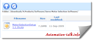
This tool is very unique and useful and lets you select servo motor based on your project requirement. Suppose you want to make a project where servo motor is required at conveyor belt, roll feeder, suspension, ballscrew etc., then this is the tool for you.
Recommended Article : Best PLC programming Books
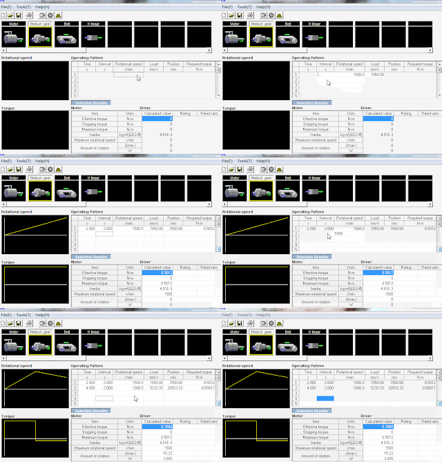
When you start Servo motor selection tool, you have to choose the purpose of your servo motor. Let say we need servo motor for conveyor belt system, then we choose the same as shown below.

After selecting your mechanical system, this tool will ask information about your components and your requirement. Like in conveyor belt it ask for reduct gear, belt & H linear values. We are keeping these setting as default for demo purpose, you can edit it as per your needs.
Recommended Article: Understanding Servo & Motion Basic
Now the next step which you have to perform is that, you will have to put your operating value. Let say I want 1500 rotation per min in 2 second interval, just fill 1500 in RPM section and 2 seconds in time section, rest is automatically calculated.
Now after entering your requirement you can click on Motor selecting icon which will show you recommended servo motor names form Omron. Now you can choose one which best suits you as per your capacity, RPM, Torque etc. requirement. You can click on judgement to see if you are selecting right servo or not.
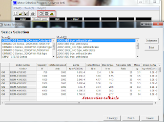
Now just click on next button after selecting your motor and print the report and send to your client or save to your project file. A sample servo motor selection report can be downloaded from this link.
Hope you found this article useful and will use to select your servo motor too. Let us also know what you think about this tool with your comments and feedback. Do stay in touch and join us at Facebook and Twitter.
Apr 22, 2013
Know about Omron Remote Assistance
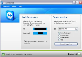
Remote assistance is a software which helps in taking remote session of other PC or system from remote location. In automation industries, this software is very useful for all commissioning engineer who are troubleshooting remotely. Now with every Omron CX-Supervisor V3, Omron Remote Assistance is also provided for free and if you are using old version and want to get this software, you can get it from Omron official website. This software is provided by Teamviewer, one of the market leaders in remote desktop control. Subscribe to Automation-Talk by Email.
Recommended article: SCADA & HMI Control through IPad, Windows, Android Devices
First of all you will need to have this software installed on your system or PC or Laptop client and main machine, whatever device you are using. You can also use your IPad, Android device to connect to remote site, though you will have to install different application for that.
To get this software first go to MyOmron.com and then click on Download tab. The route path for this software is /downloads/4.Products/Software/RemoteAssistance/.
This software can also be downloaded from Teamviewer.com official Website and it will also not contain Omron watermark to it.
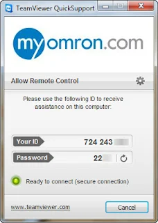
Now when you have installed this software, the software will try to connect to the Internet. If you have your firewall enabled or have any antivirus which ask to allow this application, then please allow it. After successful connection, it will show you a green indicator and will also generate user ID and password for you as shown above.
Note: This User ID and password is of Client machine
Now you can use this user ID and password from main laptop or PC to connect the client remote machine of whose password and user it you have. This is a very secure connection and if TeamViewer is not running on clinet machine, then you cannot connect to it. Now once you are connected to the remote PC, you can do your troubleshooting, program editing in that particular PC like you are using your own PC.
Nov 18, 2012
Extend Cycle Time for Omron CP1E PLC
If you want to extend maximum cycle time for your CP1E PLC for a particular cycle, then you can do this by use of WDT instruction. This instruction extends the maximum cycle time, but only for the cycle in which the instruction is executed and can be used to prevent errors for long cycle times when a longer cycle time is temporarily required for special processing. Subscribe to Automation-Talk by Email.
Related Reading: Using High Speed Counter in Omron PLC
WDT(094) instruction can be used with sub-routines, interrupt tasks and step program area. This instruction can be used to prevent a cycle time error, when there are circumstance that the cycle time will increase due to a temporary increase in processing data. The watchdog timer setting in the PLC Setup is extended by an interval of T × 10 ms (0 to 1,000 ms).
Syntax: WDT(094) [T]
where T is timer setting which specifies the watchdog timer setting between 0000 and 0064 hexadecimal or between &0000 and &0100 decimal.
For execution of this instruction you must setup the PLC timer setting which are present in PLC setting as shown below.

Note: WDT(094) can be used more than once in a cycle. When WDT(094) is executed more than once the cycle time extensions are added together, although the total must not exceed 1,000 ms. If WDT(094) cannot be executed again if the cycle has already been extended to 1,000 ms.
Oct 29, 2012
Moving Data using MOV Command in Omron PLC
In some projects, it is required to move some particular or any data to data memory of the PLC in ladder programming in Omron. In that case, we can use a simple instruction called MOV which is used to transfers a word of data to the specified word. This data movement command can be used in 3 forms viz. MOV, MOVL & MVN having different movement function as explained below. Subscribe to Automation-Talk by Email.

Different Types of MOVE Commands
1. MOV: Transfers a word of data to the specified word. Transfers data in Source to Destination. If S is a constant, the value can be used for a data setting.
Syntax: [MOV Source word Destination word]
Example: [MOV D5 D10]
Here data in D5 will be moved to D10.
2. MOVL: Transfers two words of data to the specified words. If S is a constant, the value can be used for a data setting.
Syntax: [MOVL Source word Destination word]
Example: [MOV D15 D20]
3. MVN: Also called Move Not, transfers the complement of a word of data to the specified word. MVN inverts the bits in source word and transfers it to destination word.
Syntax: [MVN Source word Destination word]
Example: [MOV D25 D30]
MOVB and MOVD are also used in transfer of specific bit and digit respectively. To test move command, you can make a simple PLC program as shown in above image and then try moving data using PLC simulator in Omron. You can check and verify it in Memory area.
Oct 17, 2012
Hotkeys for Omron CX Programmer
CX Programmer is PLC programming software which is used to program all Omron PLC's. CX programmer is a easy to use and comes with many handy shortcuts which can really save your lot of time. For an example most common shortcut is alphabet "C" which brings you the NO type of contact when press while making the ladder program in any rung. Subscribe to Automation-Talk by Email.

Omron CX Programmer Shortcut Keys
Below are some of the most common and widely used CX Programmer shortcut keys. Below hotkeys are not case sensitive.
1. C : No Contact
2. / : NC Contact
3. O : No Output Coil
4. I : Writing Instructions
5. Q : NC Output Coil
6. Ctrl+K : Force Off
7. Ctrl+J : Force On
8. Ctrl+L : Force Cancel
9. Ctrl+W : Work Online
10. Space : Find Bit
11. N : Next Address
12. L : Comment
13. B : Previous Jump
14. Ctrl+1 : Program mode
15. Ctrl+3 : Monitor mode
16. Ctrl+4 : Run mode
17. Ctrl+2 : Debug mode
18. Ctrl+F : Find
19. Ctrl+E : Begin on-line edit
20. Ctrl+Shift+E : Send on-line edit changes
Note:
1. While in Simulation mode of CX Programmer, click CTRL+JKL to quickly on, off & cancel force on go.
2. Press SPACE KEY while you have selected any bit, it will find all related bit's.
3. Press CTRL+SHIFT+W key activate simulator mode in CX Programmer.
4. Other general shortcut key like copy, cut, paste also work in CX Programmer.

