Showing posts with label How To. Show all posts

Jun 18, 2018

PLC Programming for Tank Level Measurement using Ultrasonic Sensor

In our earlier post, we saw the PLC Logic for Auto Filling of Tank using digital inputs for LOW and HIGH-Level signals. 


Today in this post, we will see how we can measure the level of a tank using the Ultrasonic/Capacitive level sensor and accordingly ON/OFF the PUMP at low and high levels.
 

PLC Programming for Tank Level Measurement using Ultrasonic Sensor

PLC Programming for Tank Level Measurement Using Ultrasonic Sensor


First of all, we need to choose the Ultrasonic/Capacitive level sensor according to our tank level height. The sensor will give a 4-20mA signal to PLC and accordingly, we will calculate the level in the tank.


PLC Logic Development:-


Now, we need to connect the analog input from the ultrasonic sensor to PLC, we have already told that in our earlier post. You can see it here.

After that, we have to write SCL (scaling instruction) in the PLC to convert the value received by PLC to the scale we want. 

For example, if the height of our tank is 5000cm, PLC will receive the 4-20ma signal and internally will convert it into a range of o to 0FA0 (hexa), and with the help of SCL instruction we will scale this value between 0 to 5000.

So that when the Ultrasonic sensor will give 4mA signal then the level in the tank will be zero and when a signal of 20mA will be received then the level in the tank will be 5000cm.

In SCL instruction, we have to define the scaling parameters in some D:-


D200 - 0
D201 - 0
D202 -5000 (hexa)
D203- 0FA0 (hexa)

Here the value 0 to 0FA0 received by PLC will be scaled to 0 to 5000 (our tank height).

Now in this PLC Program we have kept the low level at 2500cm and the high level at 4600cm. You can download the PLC program from below, we have built the PLC Program using the Omron CX-supervisor software. Both the .cxp and .pdf files are included.

Download PLC program for Tank Level Measurement.


Hope you like this PLC program on controlling your Tank according to the measurement using an Ultrasonic sensor. If you face any problem with this PLC Program or want any modification then write us in the comment section. 

Also, you can subscribe to receive the latest updates about PLC Programming languages, SCADA tutorials, HMI programming, MODBUS programming, VFD Installation., etc. subscribe to Automation-Talk by Email.

Oct 30, 2017

How To Reduce Electromagnetic Interference in Servo Drives

Motion Controllers and Servo drives are used in machines for the better controlling and accurate positioning purpose. The one thing which we should keep in mind while installing the motion control panel is to have a safe and healthy environment for the Servo Drive and Motor operation i.e the environment should be free from any Electromagnetic Interference (EMI). EMI can dramatically reduce the performance of the system and can lead to various other problems. In this post, we will see that what practices should be followed in order to have the minimum or zero effect of EMI.


Reducing EMI effect by following Standard Wiring Practices


How To Reduce Electromagnetic Interference in Servo Drives


Generally, all major servo drive and motor manufacturers have their products following CE compliance. But using CE approved components will not guarantee a CE compliant System. The whole depends upon the components In drive, interconnection procedure, and installation method. So we should follow the practices by which the EMI effect can be minimized.

Electromagnetic Interference is generally generated by High frequency switching circuit. EMI generated inside the enclosure is either conducted or radiated back inside the enclosure only, so proper measures should be taken in order to avoid EMI conducted back into the main power source. Below picture illustrates that how EMI is conducted or Radiated back to the main power source.


EMI Radiation Conduction


Steps to Follow for Reducing/Minimizing Conducted EMI Effect


In order to reduce the Conducted High-Frequency noise, an EMI filter should be installed in series with the power supply. This EMI filter should block frequencies causing Interference and also not saturates at the current level required for normal operation. The EMI filter should be installed in such a way that it blocks EMI conduction to main power supply.

Shielded and Screened cables should be used wherever appropriate. Power Supply cables should be kept separate from Signal Cables and all cables should be as short as possible. Ground wires should have sufficient cross-section area in order to minimize the Skin Effect and conduct EMI to ground. Connect the EMI filter properly as shown below.

EMI Filter Correct Wiring


How to Remove the Radiated EMI Interference:-

Several points should be kept in mind to reduce the radiation of EMI back to the main power source. If there are any holes in the enclosure than the Holes should be as small as possible. Use conducting Gasket at seams of the door. Avoid grounding the Screens/Shield at only one end, doing this can dramatically increase the radiated EMI. If you found any particular cable is creating much EMI than it can be reduced by ferrite beads.


We will summarize the important points below:-

All cables that connect to motor control should be shielded. Input power cable and Motor Output cable should be separate and positioned independently. Grounding must be done properly and all cables should be laid close to the ground plane. The motor cable shield should be connected to a motor ground terminal at motor side.

Motor Correct Wiring Procedure

The above picture shows the standard wiring procedure for better efficiency.

The shield/screen of all cables connected to the control must be grounded to the control by connecting the shield to the control’s “Ground” terminal. The cables include the motor cable, input cables, feedback cables regen/dynamic resistor cables and other control cables.Subscribe to Automation-Talk by Email.

If you strictly follow all the steps told above, then definitely the EMI effect will be minimized and will achieve better efficiency and increased life of your product. In upcoming articles, we will further discuss the more advanced things to eliminate the EMI effect completely from your system. Till then you can subscribe to Automation-Talk by Email to get all latest updates by eMail.

Feb 3, 2011

Configure Historical Trend in Intouch SCADA

As we have told in our earlier article about Trends in SCADA system i.e Real-Time and Historical Trend. In this article, we will tell you "how to configure Historical Trend in Wonderware Intouch SCADA". First of all, we will tell you what is Historical trends and its importance. As we have told Historical trends are used to view past values of the Tag and you can configure them to see any past date Data. Subscribe to Automation-Talk by Email.

Configure Historical Trend in Intouch SCADA

"Historical Trend" plays a very important role in our SCADA system as on enabling Historical data logging we can clarify what was the past value of the desired tag value. You can also see How to Configure Real Time Trend In Intouch SCADA.


How To Configure Historical Trend in Intouch SCADA


1. The most important step for "Historical Trend" is that you should enable Historical Logging. To enable historical logging in Wonderware Intouch you will have to go

Special --> Configure --> Historical Logging.


Historical Logging


2. Now when you click on Historical Logging you will see a window just check Enable Historical Logging. And click OK.

Intouch Enable Historical Logging


3. Now you have enabled historical logging and you will have to draw a historical chart. Just click on the Historical button from the task bar.

enabled historical logging


4. Now just drag this chart and double click on it to open its property. Now put the Tag which you want to Log in the Tag Name which is marked as PEN. Note that you can configure 8 tag name in One chart.

Configure Historical Trend Property


You will see many options here like color change of Trend lines, time division, value division etc. and we have marked the important once and don't forget to put them. If you have any problem you can leave a comment or you can Subscribe to Automation-Talk by Email for more upcoming tutorials.

Nov 24, 2010

How to Remove Omron PLC Password

Protecting your PLC sometimes may become a serious problem to the PLC programmer if he forgot the Password of the PLC while troubleshooting the machine. So all PLC programmer must know how to set the Omron PLC password to protect it and also they should know how to remove the Omron PlC Password. 


To remove the Omron PLC password of PLC's & CPU like CP1E, CP1H, CPM2A, CPM1A, CQM1, CQM1H, CJ1M, CP1L, CS1D, CS1H, C100H, C200H, etc. follow the below methods.


How to Remove Omron PLC Password


Steps to Remove Omron PLC Password


1. Make sure you have the backup of the program to which you don't have the password.

If you have the program then removing the password is not a big deal. You can just go to the PLC setting (See image below).

Then click on Properties and then Protection, the nyou can see you password there.


OMRON PLC programmer setting
Click on the Image to enlarge them.


How To Download Omron CX Programmer (CX-One) for Free


2. If you don't have the backup of the program and you can write a new program for it, then you can simply erase all the Memory of the PLC which will also erase the memory where the password is saved.

Normally Omron Password is saved in the Auxiliary area of the memory.

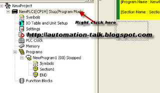
To reset Omron PLC memory, first, you will have to go Online, then click on the PLC tab. Then go to clear all memory areas and click on Initialize and click OK.

See the below Images to Understand better.


Clear all Memory area OMRON PLC


Now after clearing memory, go offline and restart the PLC. Now you will see that there is no Password in Omron PLC. Now you can write a new program in PLC memory and even upload it.

Note:- If you don't want to remove the password, then you can also download the program in PLC if its overwriting protection is not Enabled.

Hope you like the article and if you do, do not forget to share it with your friends and subscribe to Automation-Talk by Email for more such tutorials.


Receive all updates via Facebook. Just Click the Like Button Below