Protocol Converter is a device which converts one protocol into other protocol so that other device having that protocol can be operational, simply its for interoperability between devices like converter for RS232 to RS422 or RS-485 or RS422 to RS232 converter for an example. The major protocol translation messages involve conversion of data messages, events, commands and time synchronization. The simplest and most commonly used conversion is protocol conversion between Modbus RTU and Modbus TCP. Subscribe to Automation-Talk by Email.

Types of Protocol Converters
There are basically two types of protocol converter which are listed below.
1. Software Protocol Converters
2. Hardware Protocol Converters
Some of the most popular industrial automation protocols are DF-1, CAN (Controller Area Network), RS-232, RS-422, ControlNet, DeviceNet, HostLink Protocol (Omron's protocol for communication over serial links), Profibus, Modbus, Honeywell SDS, HART Protocol, EtherNet/IP etc. And some Industrial control system protocols like MTConnect, OPC, OPC UA.
Application of Protocol Converters
Protocol converters are widely used in process or industrial automation, building automation, substation automation, automatic meter reading and vehicle automation applications. If you feel reading more about our post then you can Subscribe to Automation-Talk by Email.
Jul 30, 2012
Protocol Converter for Industrial Automation
Jul 23, 2012
Can you Find the Output of this PLC Program?
For the last few months we have been discussing PLC programming and how to begin PLC programing. Today we will try to understand one basic concept of the PLC Programming ,most of us who are beginners in PLC Programming make this mistake. So we will understand the basic concept behind this plc program.
Subscribe to Automation-Talk by Email.
Solve this Sample PLC Program :-
See the below PLC program :-
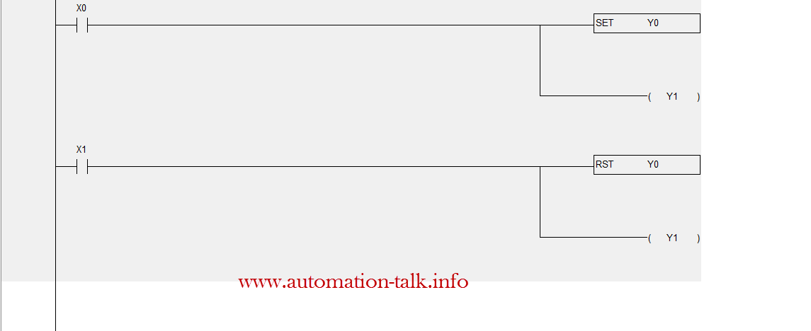
Note :- CLICK ON IMAGE TO MAGNIFY
Can you guess the output of this plc program?? If you see the above program carefully then we find that output y1 is used twice in the program and if u recall the scan cycle then from scan cycle we understand that the image of the output which is near to end rung is maintained i.e whatever the sate of output y1 connected in last rung is that will be maintained all the time irrespective of its state at rung 1.
Most of us who begin plc programming make this mistake , so we should never connect the same output at two places in the plc program.
So when we press the X0 then the output Y0 will latch but the output Y1 will not be on ( because the state of output Y1 at rung 2 is OFF ) and when we press X1 then the output Y0 will unlatch and output Y1 will be on for the time X0 is pressed.
You have to be familiar with PLC Hardware and its basic function to understand the above. But at this point of time just make one habit that never use the same output at two places in a plc program. Also beginners can see the omron PLC and its addressing method & Best PLC programming books, to get more familiar with plc programming.
Jul 22, 2012
How to Find RPM of AC Motor From Poles
What is Pole in AC Motor :-
Well pole indicates the number of magnetic poles that appear inside the motor when ac power is supplied to its power terminals. We should understand the poles always exist in set inside a motor i.e poles always are in even numbers.
How to Calculate RPM of Motor from Poles and Frequency :-
The synchronous speed of a motor is always calculated from the number of poles in conjugation with the frequency.
To calculate the RPM of a motor you just need to apply the below formula.
RPM = 120F/P
Where :-
F = Frequency
P = Number of poles
Subscribe to Automation-Talk by Email.
Below is the picture in which RPM of motor having 2,4,6,8 poles at different operating frequency of 50/60 Hz is shown

You can get in touch on with us on Facebook.
Jul 21, 2012
Star Delta PLC Program in Delta PLC
Today in this post we will discuss that how to make a star-delta PLC program in the Delta PLC. Star Delta program is required when we run a motor without VFD. Earlier we have discussed that how can we make the star delta program in Omron PLC.
How to Make Star Delta PLC Program :-&
To make a star delta program is very easy. We must know that how to name the input and output coils in delta PLC. In delta PLC inputs are addressed as X and output as Y.
Star delta program making is very easy in Delta PLC. When the start push button is pushed then the main contractor and the star contractor must go ON and at the same time timer should start and after the timer has completed the pre-set time the Star contractor should be off and the delta contractor should become on. It should be noted that the main contractor should always be on.

You can also download the Star-delta PLC program from here.
In the next post we will be discussing the electrical wiring of a star delta starter. Also you can Subscribe to Automation-Talk by Email for more PLC programming.
Jul 20, 2012
Yaskawa V7 Drive Manual
Yaskawa drives are also used in Industrial automotive companies due to there low cost and high performance. The V7 drive of Yaskawa is compact drive and operable in V/f or Open Loop Vector mode which provide higher torque at lower speeds. This Technical V7 drive manual will tell you about installation, programming parameter, fault diagnosis and troubleshooting of the drive. Subscribe to Automation-Talk by Email.

The V7 was ideally suited for applications such as conveyors, grinders, centrifuges, pumps, fans,blowers, machine tools, packaging, food processing, and commercial laundry.
Download
Manual Source: Yaskawa.com
Jul 16, 2012
Three Phase Montioring Relays from Omron
Three Phase Sequence loss relay :-
As we know that motor are the driving source and we need to protect the motor from the all faults which can come. Omron K8AB-PH1 does a nice task in protecting from the phase loss. It simultaneously monitors phase sequence and phase loss during start up as well as phase loss during operation.

Omron K8AB-PW protection relay monitors the under voltage and over voltage for a three wire / four wire power supply. We can even set the time from 0.1 to 30s and also separate outputs possible for overvoltages and undervoltages.

If you like the article Do no forget us to like on facebook!!!
Subscribe to Automation-Talk by Email.
Jul 11, 2012
Design Wireless Network of Any Plant Just by Image
How to Design IEC Standard Wireless Network for Process Plant :-
It is the need of time and technology that most of the plants are opting out for the wireless solutions in their process plants. Wireless network has got much added advantage over the wired networks. Honeywell has launched this service where the user can see in advance that how the wireless network can be set up in the plant before investing in wireless technology.
To design the wireless network scheme for your process plant all you need is the image of the plant present configuration and then follow the below step by step procedure.
Step 1 :- Log On on this HERE
Step 2 :- Upload the image and then select the type of the plot plan.
Step 3 :- Drag and drop the different wireless instruments according to your need and select the best option.
Step 4 :- You can watch the >DEMO HERE for the better understanding in order to design the WirelessHART network.
We hope that this post will help in better designing for the wireless network for your process plant. If you like our post don't forget to like us on Facebook.
Subscribe to Automation-Talk by Email.
Source/Credit :- Honeywell
Jul 6, 2012
Mitsubishi PLC A1SJ71C24-R2 Programming Cable Connection Diagram
Mitsubishi A1SJ71C24-R2 cable connection diagram will be discussed in this post. If you want to make this cable at home you can made this easily. You just need to have one DB9 male and one DB9 female port. Just see the connection diagram below.
Subscribe to Automation-Talk by Email.
How to Make Mitsubishi PLC Programming Cable :-
Just see the below diagram and make the connections as shown below in the diagram.

Just make the connections as shown above and your cable is ready. We recommend to use the shielded cable to avoid any problems. Don't forget to Subscribe and like our Facebook page.
Jul 4, 2012
NJ Series Machine Automation Controller by Omron
Omron is an industrial automation company offering the wide range of products in automation and control field. Omron offers a wide range of PLC from small to large range , today we will discuss about their new controller which is specially designed for the Machine automation and control. Subscribe to Automation-Talk by Email.
Omron NJ Series Machine Automation Controller :-
Sysmac NJ 501 machine automation controller is designed to operate in harsh environments and has inbuilt Intel® Atom™ processor. The NJ series controller is designed to offer the flexibility to users in machine control and allow real-time improvements. Some of the features include the high motion control commands , faster CPU performance and specific applications solution. You can download its user manual from below to know more about it in details.
User Manual/Operation Manual for NJ501 Omron Machine Controller :-

You can download the user copy from the below.
Download.
Credits :- Omron Uk


