Motors are the heart of any plant or industry. The origin of Motor was to convert electrical energy to mechanical energy. DC motor was the first one to be invented and was result of concepts of electromagnetism by Michael Faraday. Today DC Motors , AC Motors - Induction , Squirrel Cage , Servo and Stepper Motor are used widely. We will see in brief about all these different types of Motors used in Automation Industry.
Electrical Motors In Industries :-
1) AC Motor :- We have already discussed the history of AC Motor in our earlier post. There is two broad classification of AC motors first Induction Motor and second as Synchronous Motors.
AC Induction Motor can viewed as Transformer for easy understanding. When voltage is applied to primary of Transformer a current flows and as a result current is induced in secondary winding of transformer.
The primary can be considered as Stator and Secondary as Rotor of AC Induction Motor. The magnetic field set up in the Stator results in Induced Magnetic Field in Rotor and results in Motion. Working of AC Induction Motor discussed already.
Synchronous Motor is same as Induction motor but with different Rotor configuration. The rotor is constructed in such a way that the Rotor is able to rotate with exactly same speed as of stator field. There are two variants of Synchronous Motor - self excited and Directly excited.
2) DC Motors :- DC Motors have been used in Past over the AC motors for applications demanding Speed and Position Control . Until the Introduction of Power electronics the speed variation of DC Motor was easier. In DC Motors the field in stationary in stator and rotor field, is set up by passing current through a commutator and into the rotor assembly. There are different types of DC motors as Shunt Wound Motor, Series Wound Motor and Compound Wound Motor.Subscribe to Automation-Talk by Email
3) Stepper Motor :- As the name indicates Step Motors are used for Converting the Digital Inputs commands in to Analog motion with the help of motor controller electronics.
Stepper Motor Rotates in angular positions according to the digital pulses Inputs. There are different types of Stepper Motors namely as solenoid activated, variable reluctance,permanent magnet and synchronous inductor stepper Motor.
4) PMDC Motor :- PMDC stands for permanent magnet DC , and is mostly used in closed loop system with effective feedback system. In these Motors there is linear speed-torque curve due to permanent magnet which provide provide constant field flux at all speeds. This Motor generates high starting or acceleration torque with light weight and thus used for rapid positioning applications.
5) Servo Motor :- Servo Motor works on servo-mechanism , best for closed loop applications . A controller issue commands for position/speed/torque control of motor shaft. "Servo" is a very big word to understand and we will be discussing more about servo drives, controllers and closed loop system in details in our further posts.
Till then you can subscribe to get all updates in yours In-box. Subscribe to Automation-Talk by Email.
Feb 28, 2011
Feb 27, 2011
Servo Motor Basics - Closed Loop System
Servo has been a Key Solutions for Applications demanding high accurate and fast positioning closed loop feedback systems. What makes Servo so special? What is there in Servo Motors which cant be done by AC Induction Motors? We will see in this post the functioning of servo motor.
Servo Controller Fundamentals :-
Servo Controller has made possible to reduce the transient response time along with reducing the steady state errors. Better the Transient response time the more is the System bandwidth and thus allowing for faster response and better machine throughput. Less Steady state errors directly indicates for better accuracy.
Below you can see the basic block diagram of servo-mechanism. AC power supplied to Servo System is divided in to two levels as Low and High Level internally by controller electronics section. The low level power is given to Servo Amplifier , which in turn amplifies or increases this signal for motion of servo motor or load.

The low level signals must be amplified as higher voltage is required to rotate the Servo Motor at higher speeds and more current is required for Heavier loads demanding more torque. As we know that Servo System is closed loop System , so when Servo Motor Moves , encoder attached with it also moves and the feedback is received by Controller/Servo Amplifier.
The Servo Controller then looks at this Feedback by Encoder to decide whether the Load is moving properly or not. Suppose for example a command is issued for 5000mm movement of Load and feedback is received for only 4500mm , so controller will issue a command for another 500mm movement. So this is closed loop system and process continues on.
The controller always monitors the Command Signal Issued and the Feedback Signal , they both have t be matched for 100 percent accuracy and zero error. The Command Signal and feedback Signal are compared regularly and corrections are made. So servo is not a single device rather it is a collection of several devices.
We will be discussing more about servo basics and facts , till then you can subscribe to get all updates directly to your mail-box. Subscribe to Automation-Talk by Email.
Feb 23, 2011
Baldor Microflex Drive Resolver Cable Diagram
In our earlier sections we saw the Baldor Drive Communication cable Diagram. In this Post we will see the Cable Diagram of Resolver Feedback Cable. You can also buy this cable from Baldor but its very costly , its very easy to make , so you can also make it at your own.
Baldor Microflex Servo Drive Resolver Cable Connection Diagram
See the below diagram for making the Resolver motor to drive feedback cable.

We recommend to use shielded cable for making this cable.
If you have any doubts you can write in comment section.
Subscribe to Automation-Talk by Email.
Baldor Microflex Servo Drive Resolver Cable Connection Diagram
See the below diagram for making the Resolver motor to drive feedback cable.

We recommend to use shielded cable for making this cable.
If you have any doubts you can write in comment section.
Subscribe to Automation-Talk by Email.
Feb 20, 2011
How to Find/Limit AC Motor Inrush Current
Inrush current problems while start up of the solid state equipment's as copier, computer and magnetic devices like motor, drives a large amount of current flows and this value of current is several times of steady state value and known as Inrush current. There is no actual known formula for calculation of this Inrush Current value but yes we can determine an approximate value.

When a Motor is started or Transformer energizing takes place then the inrush current can cause a imbalance in the power circuit. However, this inrush current is for few seconds but we should take appropriate actions for this problem.
We will discuss the few major actions which can be adopted to limit the Inrush Current value.
1) Try to keep the Large Ratings Motor on a separate power supply, it will prevent the voltage sag problem.
2) Use Inrush Current Limiting Thermistor, its resistance decreases the temperature increases.
3) Use Series capacitors for distribution circuit of large Rating Motors.
The value of the Inrush Current at start Up can be found out using the Clamp Meter and noting down the measured Value and after that try to use the one of the above method to limit the value. After implementing the method just measure the Value of Inrush Current again and check whether it is reduced or not. Subscribe to Automation-Talk by Email for more articles.

How to find AC Motor Inrush Current
When a Motor is started or Transformer energizing takes place then the inrush current can cause a imbalance in the power circuit. However, this inrush current is for few seconds but we should take appropriate actions for this problem.
How to Limit Inrush Current Value
We will discuss the few major actions which can be adopted to limit the Inrush Current value.
1) Try to keep the Large Ratings Motor on a separate power supply, it will prevent the voltage sag problem.
2) Use Inrush Current Limiting Thermistor, its resistance decreases the temperature increases.
3) Use Series capacitors for distribution circuit of large Rating Motors.
The value of the Inrush Current at start Up can be found out using the Clamp Meter and noting down the measured Value and after that try to use the one of the above method to limit the value. After implementing the method just measure the Value of Inrush Current again and check whether it is reduced or not. Subscribe to Automation-Talk by Email for more articles.
Feb 18, 2011
Panasonic FP0/FP0R Series PLC & NV HMI Communication
NV HMI by Omron is capable of communicating with a wide range of PLC of different make. In our earlier articles we saw the NV HMI Communication with Panasonic FPΣ Series PLC and NV HMI & Panasonic FP-X-series PLC Communication. In this article we will see the step by step procedure of NV HMI communication with FP0/FP0R Series PLC .
Panasonic FP0/FP0R Series PLC and NV HMI Serial Communication :-
The NV HMI can be connected at Tool Port or COM 1 for RS232 Communication. We will see the connection diagrams for both the type of communication scheme.
FP0/FP0R-series Tool Port Connection with NV HMI
For making connections via Tool port we need a Mini DIN 5-pin connector. Just make the connections as shown below.
PLC Tool Port----------------------------------------------------------NV HMI
PIN 1 (SG)-------------------------------------------------------------Terminal 8 (SG)
PIN 2 (SD)-------------------------------------------------------------Terminal 5 (RD)
PIN 3 (RD)-------------------------------------------------------------Terminal 4 (SD)
FP0/FP0R-series COM Port Connection with NV HMI
PLC COM 1 -----------------------------------------------------------NV HMI
PIN S--------------------------------------------------------------------Terminal 5(RD)
PIN R--------------------------------------------------------------------Terminal 4(SD)
PIN G--------------------------------------------------------------------Terminal 8(SG)
Now you can connect the PLC as per yours requirement , and we are done with the hardware connections , Just we have to define some of the communication parameters at both the HMI and PLC side.
Open NV HMI software , NV Designer it is used to develop screens in NV HMI. Just create a new project and in the PLC type select as "Panasonic FP Series." After this got to PT-------NV Configuration and make Baud Rate as 19200 Kbps , Data Bit as 8 , Stop Bit 1 and Parity as Odd.
Also make the following Communication Parameters settings at the PLC side.
Communications mode------>> Computer link
Baud rate------>> 19,200 bps
Data bits------>> 8
Stop bits------>> 1 Parity Enabled, odd
End code------>> CR
Start code------>> No STX
Unit number------>> 1
Modem connection------>> No connection
You can also subscribe to get all latest updates in HMI , PLC Programming , VFD Installation and SCADA Scripts.Subscribe to Automation-Talk by Email.
Configure KEPServer For Allen Bradley DH+
KEP OPC Server is a very popular serve and allow connection to almost all the device using OPC. If you want to connect your PLC to a third party Software you can use KEP server OPC as it is one of the best in the Market. In this tutorial we will learn some basic steps and how to configure your KEPServer for Allen Bradley DH+ Protocol. The tutorial will tell you how to add a new channel in KEP server. Subscribe to Automation-Talk by Email.
Configure KEPServer For Allen Bradley DH+
1.Open your Kepserver. If you don't have try Demo.
2.Now click on Click to Add Channel

3.You will get a New Channel Window. Name your Channel and click Next.

4.Select your Device Driver here we will use Allen Bradley DH+ Device Driver and do Next.

5. Now you will get the Optimization window, no need to modify it.


6.Now you will have to select your Interface Card configuration. Select accordingly and click Next and select your Network (DH+).See above image.
7. Now select Station ID for your Card. Say 0.Now click Next and also select Baud rate.


8. Now you will have to select Memory Address. Select your D. We have selected D4000. See above Image.
9. Select None as Interrupt Level. Or you can select according to your self.


10. Now you will see Summary of all these process. see it and if you want to make any change click back. After it you can add your Device as configuration is complete.

If you have any query in this tutorial please let us know. Till then Subscribe to Automation-Talk by Email for more such Tutorials.
Different Types Of Encoder Used In Automation Industry
In a wide range of Applications in Industrial Automation , One device which is all time favorite for feedback purpose is "Encoder". As it has got capability to be used in Rugged and Noisy Environment , Low cost so still its best choice for feedback purpose and dominates the market.Here in this post we will see about the different output types and Encoder Operating Principle.
||Different Types Of Encoder In Automation Industry||
There are two types of Encoders broadly either in rotary or linear configurations. Every Encoder comes with a predefined PPR and the Maximum Frequency. Let us see how a rotary optical encoder gives the quadrature format. A rotary optical encoder has two output wires as A and B for giving out the quadrature format output. This encoder also Provides the Index pulse for every single rotation completed.
Construction of Rotary Optical Encoder:-
The most common configuration for this type of encoder consists of series of Opaque Parts. The Encoder unit consists of Light Emitting Diode(LED) or Pair of sensor for Giving out the signal for A and B.Now the Opaque Array Segments are arranged in such a way that when it is rotated the A and B signal will be 90 degree to each other. The Index pulse provided after every single rotation of Encoder Shaft can be used for Homing Purpose. See the Below Picture for the overview of Construction part and A , B and I pulses.

Image Source:- automation.com
One of advantage of Index Pulse is used for "auto-correct" feature. The Index pulse will be fixed for the same position of Motor's shaft for every rotation and if there is noise and somehow the number of counts increase or decrease then we can get to know and auto-correct the same.
But with the Incremental Encoders there is a problem ,when we start our system we can't get to now the actual position , so we home the machine . But here comes the another solution and answer is "Absolute Encoders" , with these encoders it is possible to know the actual location every time. These comes in a wide range of Outputs , up to 25 bits.
What is the Difference Between Incremental & Absolute Encoder.
But in earlier time when there were No LED or sensor for Generating the 90 deg offset pulses , non-optical position encoder were used. These are known as "Resolver".The Output of Resolver is in Sinusoidal waveform.
Another Type of Encoder is Magnetic Encoder. The best advantage of this type of Encoder is that the sensor and the encoding disk are not in contact , so it can be rigid packed and a very good solution for noisy and dirty operating conditions.
You can subscribe to get all latest Updates about Encoders, PLC programming and SCADA Script.
Subscribe to Automation-Talk by Email
Feb 15, 2011
Omron SmartStep Servo User & Operation Manual
 SmartStep is the Servo system series from Omron and comes with many features. The servo Package comes in different different rated output from 100W to 750W in Flat Servo Motor and from 30W to 750W Cylindrical servo motors. This servo Package name start from R7 and Servo Drive Nomenclature start from R7D and Servo Motor Nomenclature start from R7M. Subscribe to Automation-Talk by Email.
The SmartStep motors offer the simplicity and cost-effectiveness of a stepper with the added advantages of a servo system. It is available in many Sizes like 30W to 800W, rated speed 3,000 rpm.
You can see the below links for Manual of Omron SmartStep Servo
SmartStep Users Manual
SmartStep Operation Manual
Source: Omron UK
These manuals are in English for other language you can make a request.
Feb 13, 2011
KEEP Instruction - Omron PLC Programming Tips
Generally, while making the PLC program, we have to use SET and RESET instructions in our PLC program on many rungs. For using SET and RESET we have to write these instructions at two different rungs, and for every BIT that has SET it has to RESET at some condition. In this tutorial, will discuss KEEP instruction, where we can define both above instructions.

There is a better instruction available in CX-Programmer for such situation, CX- Programmer is the software used to program the Omron PLC, which can do your job easy. KEEP is the instruction name and in this instruction, we can define the SET and RESET conditions at same rung.
See the below picture.

Note:- Click on the picture for a clear view.
When W2.0 turns ON, the designated bit will go ON and stay ON until reset, regardless of whether W2.0 stays ON or goes OFF. When W3.0 turns ON, the designated bit will go OFF(w4.0).
KEEP Instruction can be used to create flip-flops as shown below.

Note:- Click on the picture for a clear view.
If a holding bit is used for BIT to be SET, the bit status will be retained even during a power interruption. KEEP can thus be used to program bits that will maintain status after restarting the PLC following a power interruption. An example of this that can be used to produce a warning display following a system shutdown for an emergency situation is shown below.

Note:- Click on the Picture for a clear View.
Important Notes
i) If S and R are ON simultaneously, the reset input takes precedence.
ii) The set input (S) cannot be received while R is ON.
We will be posting more articles on PLC Programming tips, till then you can subscribe to get all updates in yours Inbox. Subscribe to Automation-Talk by Email.

KEEP Instruction - Omron PLC Programming Tips
There is a better instruction available in CX-Programmer for such situation, CX- Programmer is the software used to program the Omron PLC, which can do your job easy. KEEP is the instruction name and in this instruction, we can define the SET and RESET conditions at same rung.
See the below picture.

Note:- Click on the picture for a clear view.
When W2.0 turns ON, the designated bit will go ON and stay ON until reset, regardless of whether W2.0 stays ON or goes OFF. When W3.0 turns ON, the designated bit will go OFF(w4.0).
Recommended Article: PLC Logic Auto-Filling Tank
How to Make Flip-Flop using KEEP Instruction in PLC
KEEP Instruction can be used to create flip-flops as shown below.

Note:- Click on the picture for a clear view.
If a holding bit is used for BIT to be SET, the bit status will be retained even during a power interruption. KEEP can thus be used to program bits that will maintain status after restarting the PLC following a power interruption. An example of this that can be used to produce a warning display following a system shutdown for an emergency situation is shown below.

Note:- Click on the Picture for a clear View.
Important Notes
i) If S and R are ON simultaneously, the reset input takes precedence.
ii) The set input (S) cannot be received while R is ON.
We will be posting more articles on PLC Programming tips, till then you can subscribe to get all updates in yours Inbox. Subscribe to Automation-Talk by Email.
Feb 11, 2011
NV HMI & Panasonic FP-X-series PLC Communication
Panasonic FP-X series PLC can be connected with NV HMI through RS232 or RS485/RS422 Mode. All the internal bits and Data Registers can be accessed through HMI and Application screens can be designed accordingly. Panasonic FP-X series PLC have Tool port and COM port through which connections can be made.
How to Connect Panasonic FP-X-series PLC Through Tool Port(RS232) :-

To make the connection via Tool Port on PLC with omron NV HMI we need a Mini DIN 5-pin
connector with loose wires at other End. Make the hardware connections as shown below.
PLC Tool Port---------------------------------------------------------NV HMI
PIN 1 (SG)-------------------------------------------------------------Terminal 8 (SG)
PIN 1 (SD)-------------------------------------------------------------Terminal 5 (RD)
PIN 1 (RD)-------------------------------------------------------------Terminal 4 (SD)
After making this connection we have to set the communication format setting in the PLC system registers. Make the following settings.
In the system register 410(Tool port unit number) set 1 , in register 412 (Modem connection) set No connection , in register 413 set Data length 8 bits, Parity check Enabled(odd), Stop bits 1 bit, End code CR (fixed) and Start code No STX (fixed).
Connecting to an FP-X-series PLC Through COM Port with NV HMI|RS232 Communication :-

The NV HMI communication with Panasonic FP series PLC can also be done through COM port on the PLC. Just make the connections as shown below.
PLC COM 1 -----------------------------------------------------------------NV HMI
PIN SD--------------------------------------------------------------------Terminal 5(RD)
PIN RD--------------------------------------------------------------------Terminal 4(SD)
PIN SD--------------------------------------------------------------------Terminal 8(SG)
Note:- Also short the RS and CS at the PLC side. Connect the RS and CS terminals on the AFPX-COM1.
Panasonic FP-X series PLC RS485 Communication with Omron NV HMI:-
There can be situation when some other external hardware devices are connected to Tool port and COM 1 , so we can have the Communication of NV HMI through RS485. Make the connections as shown below for RS485.
PLC COM 3-----------------------------------------------------------------NV HMI
PIN S+ ------------------------------------------------------------------Terminal 4 (+SD)
PIN S- ------------------------------------------------------------------Terminal 5 (-SD)
NOTE-Short the Terminal 4 with 6 and Terminal 7 with 8. Turn ON pins 1 to 4 on the switch on the back of the AFPX-COM3.
UPDATED :-
Panasonic FP-X series PLC RS422 Communication with Omron NV HMI:-
Also you can make the connections using the RS422. Make the connections as shown below.
PLC COM 3---------------------------------------------------------------NV HMI
PIN S+ ------------------------------------------------------------------Terminal 6 (+RD)
PIN S- -------------------------------------------------------------------Terminal 7 (-RD)
PIN R+ ------------------------------------------------------------------Terminal 4 (+SD)
PIN R- -------------------------------------------------------------------Terminal 5 (-SD)
NOTE-Short the Terminal 7 with 8. Turn OFF pins 1 to 3 and turn ON pin 4 on the switch on the back of the AFPX-COM3.
So you have got 4 choices to make the communication as you desire. After making the hardware connection we also have to define the Communication Settings at PLC and HMI side.
Communication Parameter Settings in HMI and PLC :-
Open the NV designer , it is used to make screens in NV HMI. Create a new Project in the PLC type select as "Panasonic FP Series." After this got to PT-------NV Configuration and make Baud Rate as 19200 Kbps , Data Bit as 8 , Stop Bit 1 and Parity as Odd.
PLC Communication settings have been told earlier.
Also you can subscribe to get all updates in yours Inbox , we will be soon posting the NV HMI communication with Panasonic FPΣ Series, FP0/FP0R Series , FP-e Series and MEWNET FP2/FP2SH Series.Subscribe to Automation-Talk by Email.
Mitsubishi MELSEC-Q Series RS232 Communication with Omron NV HMI
As told earlier that NV HMI is capable of communicating with Mitsubishi PLC series. We already discussed the NV HMI communication with MELSEC-FX2N/FX3U/FX3UC Series PLC and NV HMI Communication with Mitsubishi MELSEC-FX1N Series. Here we will see the step by step procedure of configuration of NV HMI with Mitsubishi MELSEC - Q series PLC.
||Mitsubishi MELSEC-Q Series RS232 Communication with Omron NV HMI||
Omron NV HMI can be connected with MELSEC-Q series PLC either via Mitsubishi Serial Communications Module or through RS-232C Port on Q00 or Q01 CPU. Lets see the connection scheme for both the types.
Connecting to the MELSEC-Q Series (Serial Communications) :-
To connect via Serial Communication Module make the communication connections as shown below.
Mitsubishi Serial Communications Module---------------------------------NV HMI
PIN 2 (RD)-------------------------------------------------------------------Terminal 4 (SD)
PIN 3 (SD)-------------------------------------------------------------------Terminal 5 (RD)
PIN 5 (SG)-------------------------------------------------------------------Terminal 8 (SG)
Note :- Also short the PIN 4 with with PIN 6 , PIN 7 with PIN 8 at the PLC side.
Connecting to RS-232C Port on Q00 or Q01 CPU :-
Also the communication between NV HMI and Mitsubishi MELSEC- Q series PLC can be done via making connections at Mini DIN 6-pin connector on Mitsubishi PLC. Make the connections as shown below.
PLC DIN Connector------------------------------------------------------NV HMI
PIN 1 (RD)-------------------------------------------------------------------Terminal 4 (SD)
PIN 2 (SD)-------------------------------------------------------------------Terminal 5 (RD)
PIN 3 (SG)-------------------------------------------------------------------Terminal 8 (SG)
Note :- Also short the PIN 5 with with PIN 6 , PIN 7 with PIN 8 at the PLC side.
Now after making the hardware connections as shown above we are done with the half part. Now we just have to make some Communication Parameter Settings at the HMI and PLC side.
||Settings in NV Designer for Communication With Mitsubishi MELSEC-Q Series PLC||
NV Designer is the HMI software used to make the screens in NV HMI. Open the NV designer software , Create a New Project and select the proper NV HMI Model which you are using and after that in PLC Type select "Select Mitsubishi MELSEC-Q (Serial Communication) Series" and then click Next and select System Memory Area accordingly.
Note :- Select Mitsubishi MELSEC-Q (Serial Communication) Series even when connected
directly to the RS-232C port on the Q00 or Q01 CPU.
Now we have to define Communication Parameters Both at HMI and PLC side. To set the Communication Parameters in the NV Designer go to PT----NV Configuration and under Communication Parameter Tab select baud Rate as 19200Kbps , Data Bit as 8 , Stop Bit 1 and Parity as Odd and check sum Enabled.
Note :- The NV-series PTs support QnA-compatible 4C frame type 4.
After making these settings , similar things have to be done in PLC Programming software of Mitsubishi PLC GX - Developer . Make the following communication parameter.
Station number---------->> 0
Baud rate---------->>19,200 bps
Data bits---------->> 8
Stop bits---------->> 1
Parity---------->> Odd
Checksum---------->> Enabled
Interface---------->> RS-232C
Communications protocol---------->> Type 4
After doing all the above steps you will be able to access the PLC internal bits and Data words through HMI. You can also subscribe to get all latest updates in yours Inbox.Subscribe to Automation-Talk by Email.
Feb 8, 2011
PLC Programming for Printing Machine - Omron Zen PLC
Here in this Post we will see the PLC Programming of a Printing Machine using the Omron Zen PLC. ZEN PLC by Omron is very micro PLC and can be used for small applications. In this Printing Machine there are four inputs and 4 outputs. The Logic of Operation according to the inputs conditions is as follows.
||PLC Programming for Printing Machine - Omron Zen PLC||
In this Printing Machine there are four Inputs and Four Outputs and the PLC Logic as Follows. When the Confirmation Input Is on , then there are Two sensor Inputs for the detection of Paper , these two inputs come at the same time , when these two inputs are on then the Cycle starts. There is One Input for Rotation . When Cycle Starts output Q0 is on and after Two Pulses of Rotation Input output Q1 is on , after 5 pulses Q2 on and after 8 pulses Q3 on. When the Signal for paper detection goes then the output starts becoming off exactly in the same manner as they were ON.
That is the off cycle is as , first Q0 off , after two pulses Q1 off , after 5 pulses Q2 off and after 8 pulses Q3 off. But what if the cycle is started and in between the Paper detection sensor signal goes? Well in this case the Cycle will continue but in a modified form that is outputs will become On one by one. Let us take one example , that cycle is started and when Q0 is on the paper detection signal goes , then after 2 pulse Q1 will on and Q0 will off , and After 5 pulses Q2 will on and Q1 will off and so on.
This application is designed using the Omron Zen PLC , as there are not Typical Instructions available in Zen PLC so the PLC Logic is purely made by Bit Logic. We have included both the.cxp and .pdf files.
Download PLC Program for Printing Machine.
Update :- Many users mailed us saying that the program has got some error , now that bug has been removed and You can Download the latest Version of PLC Program From Below.
Download New PLC Program for Printing Machine
Also you can subscribe to get all the latest PLC Programming Updates in Yours Inbox.
Subscribe to Automation-Talk by Email.
Feb 6, 2011
Omron RS232 PLC Programming Cable
Omron PLC have a RS232 port on it which can be used for programming purpose. We can program the PLC through this Rs232 Port in PLC. It is just a simple Straight RS232 cable which can be used for programming Omron PLC. There is 9 pin Female port on PLC and 9 Pin Male port on PC.
Omron RS232 PLC Programming Cable||PC to Omron PLC Communication Cable
See the below connection diagram for making the Omron PLC Programming Cable.

You can subscribe to get all latest PLC Programming cable Updates in your Inbox.
Subscribe to Automation-Talk by Email.
Omron RS232 PLC Programming Cable||PC to Omron PLC Communication Cable
See the below connection diagram for making the Omron PLC Programming Cable.

You can subscribe to get all latest PLC Programming cable Updates in your Inbox.
Subscribe to Automation-Talk by Email.
Proface GP Sereis HMI to PLC Communication Cable
Proface HMI GP series has a 20 Pin Connector for connecting to PLC . Here we will see the communication Cable connection diagram of cable between Proface GP HMI and Omron Sysmac C series PLC. Omron Sysmac C series PLC has D type 9 Pin female connector. So to make this Cable you need a 20 pin D type connector and one D type 9 Pin Male connector.
||Proface GP Sereis HMI to PLC Communication Cable Connection Diagram||
See the below diagram to make cable and make the connections accordingly.

Note :- We recommend to use a shielded cable for this and make sure to connect the shield at Pin 1 at PLC side for proper and fast communication.
You can subscribe to get all PLC Programming cables Diagram Updates in yours Inbox.
Subscribe to Automation-Talk by Email.
PLC Programming For Pump Running Cycle
Pump Running Sequence have to be defined in many applications where we have 4 or 5 pumps and we want the running of 2 or 3 pumps at a time. It may be also possible that we may want to Operate the pump according to the Level. Here in this article we will see the PLC programming for running Sequence of Pump according to level.
PLC Programming For Pump Running Cycle| Pump Running Sequence
Here we will take a example that there is a wet well and 3 pumps are there in the wet well, and there is one Ultrasonic sensor for Level measurement. The operation of Pumps will be according to Cycle , and three cycles are defined as below.
Cycle I - Pump 1 and Pump 2 Run.( Pump 3 on stand By)
Cycle II - Pump 2 and Pump 3 Run.( Pump 1 on stand By)
Cycle III - Pump 1 and Pump 3 Run.( Pump 2 on stand By)
After cycle III the Cycle I will again restart. In any cycle if one of the Pumps fail or trip then the standby pump will come in Operation.
||PLC Logic for Cycle|Pump Operations||
The operation of Pump will be according to level. Let us take the height of wet well as 1000MM and Ultrasonic Sensor is there for level measurement , when the level reaches 50 MM Pump 1 will start and when level reaches 500MM Pump 2 will start , so the level will come down and when level again comes at 20MM the cycle will change and next cycle will Start and this process continues on.
PLC Inputs :-
Analog Input - 2001 Ultrasonic Sensor
0.0 - Pump 1 Trip
0.1 - Pump 2 Trip
0.3 - Pump 3 Trip
PLC Outputs :-
100.0 - Pump 1 Run
100.1 - Pump 2 Run
100.2 - Pump 3 Run
We here are making the PLC Logic using the Omron CJ1M PLC , however the Logic can be made in any PLC after Understanding the PLC Program. CX-Programmer is the the PLC Programming software for programming the Omron PLC.
You can download the PLC Program from below , both .cxp and .pdf files are attached.
Download PLC Program for Pump Running Sequence.
Note :- Before studying this PLC Program you should know Analog Input connection and Its Programming.
You can learn the complete step by step PLC Programming here in Automation Talk , You can see more Sample PLC Programs.
If you have any doubts regarding PLC programming then you can write in comment section and also you can subscribe to get all latest updates in PLC Programming,SCADA tutorials and VFD Installation.Subscribe to Automation-Talk by Email.
How To Connect GSM MODEM For Sending SMS Through SCADA
GSM MODEM are widely used in Remote SCADA or Controlling any process through SCADA or getting any value to SCADA. The most widely used of GSM Modem in Automation is to send Alarm Message when ever there is a Alarm Process which is generated by our SCADA system. In this tutorial we will tell you how to connect and configure your GSM Modem for Sending SMS through SCADA system. In this we are Using Windows XP Operating System. We have also posted Article on SMS Sending SCADA Script and AT command used for SMS sending. Subscribe to Automation-Talk by Email.
How To Setup a GSM MODEM For Sending SMS Through SCADA
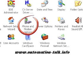
1. Go to Phone and MODEM Options of your Computer in which you want to connect GSM MODEM. You can go to Phone & MODEM through Control Panel.
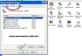
2. Double click in Phone & MODEM Options and click on Modem Tab and then to ADD (as you have to ADD a New Modem).
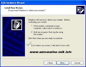
3. Now Check Don't Detect My Modem and click On Next. You can also choose Auto detect Method. If Auto method Don't work then use Manual Method.
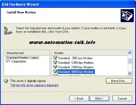
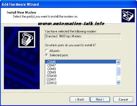
4. Now Select Standard Modem and from right list choose your baud rate you are going to Use. We choose 9600 which is standard.
5. Now choose your COM port to which your Modem is connected and click Next.
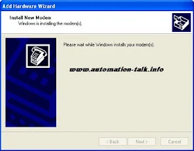
6. Now it should show a window which will tell you that Window is installing Modem.
7.After that you Modem will be successfully Installed and click Finish.
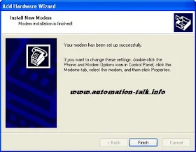
You can check installed MODEM at Device Manager & check it's Working if it is installed Successfully or Not. Or Just use Hyper-terminal and AT command to check. You can also Subscribe to Automation-Talk by Email to get more such useful tutorials.
How To Setup a GSM MODEM For Sending SMS Through SCADA
1. Go to Phone and MODEM Options of your Computer in which you want to connect GSM MODEM. You can go to Phone & MODEM through Control Panel.

2. Double click in Phone & MODEM Options and click on Modem Tab and then to ADD (as you have to ADD a New Modem).

3. Now Check Don't Detect My Modem and click On Next. You can also choose Auto detect Method. If Auto method Don't work then use Manual Method.

4. Now Select Standard Modem and from right list choose your baud rate you are going to Use. We choose 9600 which is standard.

5. Now choose your COM port to which your Modem is connected and click Next.

6. Now it should show a window which will tell you that Window is installing Modem.

7.After that you Modem will be successfully Installed and click Finish.

You can check installed MODEM at Device Manager & check it's Working if it is installed Successfully or Not. Or Just use Hyper-terminal and AT command to check. You can also Subscribe to Automation-Talk by Email to get more such useful tutorials.
Feb 5, 2011
NV HMI RS232/RS422 Interface With Mitsubishi MELSEC-FX2N/FX3U/FX3UC Series PLC
NV HMI by Omron is capable of communicating with wide range of PLC's. We already told its communication with Mitsubishi MELSEC-FX1N Series. In this post we will see the step by step procedure of NV HMI communication with MELSEC-FX2N/FX3U/FX3UC Series through RS232 and RS422.
||NV HMI RS232/RS422 Connection With MELSEC-FX2N/FX3U/FX3UC Series PLC||
NV HMI can be connected with FX2N/FX3U/FX3UC Series PLC with RS232 or RS422 , first of all we will see the connections required to communicate via RS422. To communicate via RS422 the connections have to be made at the tool port on PLC . See the below connection diagram for Rs422 Connection between Mitsubishi and NV HMI.
Mitsubishi PLC tool port-------------------------------------------NV HMI
PIN 1 (-RD)-----------------------------------------------------------Terminal 5 (-SD)
PIN 2 (+RD)-----------------------------------------------------------Terminal 4 (+SD)
PIN 4 (-SD)-----------------------------------------------------------Terminal 7 (-RD)
PIN 7 (-SD)-----------------------------------------------------------Terminal 6 (+RD)
Note:- Also short the Terminal 7 and 8 at the NV HMI Side.
Also the NV HMI can be connected via RS232 using the PLC adapter , if you wish to communicate via RS232 then make the connection as depicted below.
Mitsubishi PLC Adapter-----------------------------------------------------NV HMI
PIN 2 (RD)---------------------------------------------------------------------Terminal 4(SD)
PIN 3 (SD)---------------------------------------------------------------------Terminal 5(RD)
PIN 5 (SG)---------------------------------------------------------------------Terminal 8(SG)
Note:- Short the PIN 1 and 4 at the PLC adapter side.
Important:- The NV3W model for RS-442A cannot communicate with an FX-series PLC through an RS-422A or RS-485 Adapter.
After making the hardware connections as shown above we just have to make some communication parameter settings in the NV HMI software and PLC Programming Software.
Open the NV designer and start a new Project and in the PLC type select as "Mitsubishi MELSEC-FX2N Series" and after creating project click on the PT --- NV Configuration and make Baud Rate 9600 . Data Bit 7 , Stop Bit 1 and Parity as even.
At the PLC side make D8120=0 for proper communication to take place.
After this you can design the HMI screens as per the application and access the PLC bit devices and word Devices. Let us see the Bit devices accessible through the NV designer HMI software.
Bit Devices :-
Input relays ----------->>>X 0000 to X 0337
Output relays ----------->>>Y 0000 to Y 0337
Auxiliary relays ----------->>>M 0000 to M 3071
State relays ----------->>>S 0000 to S 0999
Timer contacts ----------->>>TS 0000 to TS 0255
Counter contacts ----------->>>CS 0000 to CS 0255
Word Devices:-
Input relays ----------->>>X 0000 to X 0320
Output relays ----------->>>Y 0000 to Y 0320
Auxiliary relays ----------->>>M 0000 to M 3056
State relays ----------->>>S 0000 to S 0976
Timer current values ----------->>>TN 0000 to TN 0255
16-bit counter current values ----------->>>CN 0000 to CN 0199
32-bit counter current values ----------->>>CN 0200 to CN 0255
Data registers ----------->>>D 0000 to D 7999
If you want to get all latest Updates in PLC Programming, VFD Installation and SCADA Tutorials then dont forget to Subscribe.
Subscribe to Automation-Talk by Email.
Feb 4, 2011
Troubleshooting with PLC Problems

Many a times it happens in the industry that a particular machine is not operating correctly or there is an error in some process. The reason can be numerous for these kind of problems like it is possible that some input is malfunctioning or processor of PLC is giving some problem. In this post we will discuss the general problems encountered.
||How to Troubleshoot PLC Related problems||
To check out the problems whether it is related to PLC for field devices , first of all connect to the the PLC and upload the PLC Program . Now every PLC Programming software have the feature to check the Error Log. Check out the Error Log in PLC and see if there are any errors.
There can be two types of Errors either Fatal or Non fatal , if there is Non-fatal error then simply clear it and if Fatal error is there then note down the code of error and check out the meaning of Error Code in the PLC user Manual.
The Fatal or Non Fatal errors can be easily monitored as every error has its unique code and necessary action can be taken to prevent the error.
The Fatal error is generally comes due to improper I/O allocation in PLC or Memory of the program is more than the PLC memory , due to battery , there can be various reasons , just check out the error code in manual and there you will also find the necessary steps to be taken to remove the error.
But sometimes it happens that a PLC Panel is installed in some machine and suddenly the machine stops to work and we also found that there is no problem in PLC. So in this case definitely there is some problem in the I/O connected with PLC. Yes we can identify that which input or output is malfunctioning.
Upload the PLC Program and monitor online and one by one check all the inputs and find that is there input is coming in PLC and similarly repeat this for the outputs. If some Input or Output device signal is not coming in PLC then definitely there is some problem in that , it can be due to wrong wiring or loose connections.
Also there can be situation that when all inputs and outputs devices signal are coming to PLC but still the machine is not operating , then it may be possible that Interlocking has been done in PLC , so in the PLC Program look out for the Interlock (IL) Instruction and check its condition and rectify the same.Subscribe to Automation-Talk by Email.
Feb 3, 2011
Microflex Baldor Drive Programming Cable
Baldor is a well known name in the field of Servo Drives and Motion Control Products. Microflex is one of the range of Servo Drives Manufactured by Baldor. There is one RS232 DB 9 Male connector on the drive for Connecting to the Computer for the Programming/Auto-Tuning purpose.
We will see How to make Baldor Microflex Family Connecting Cable to PC.
|| Baldor Microflex/Mint Drive Communication Cable Connection Diagram||
There is one Rs232 DB9 Male Port provided on the drive for its interfacing with the PC. We will see the Connection Diagram of this Baldor Drive.

Make the Cable as in above Diagram and we recommend you to use the shielded cable and connect the shield to the body of connector at either of one side.
You can subscribe to get all HMI , PLC Programming Cables in Yours Inbox.
Subscribe to Automation-Talk by Email.
Configure Historical Trend in Intouch SCADA
As we have told in our earlier article about Trends in SCADA system i.e Real-Time and Historical Trend. In this article, we will tell you "how to configure Historical Trend in Wonderware Intouch SCADA". First of all, we will tell you what is Historical trends and its importance. As we have told Historical trends are used to view past values of the Tag and you can configure them to see any past date Data. Subscribe to Automation-Talk by Email.

"Historical Trend" plays a very important role in our SCADA system as on enabling Historical data logging we can clarify what was the past value of the desired tag value. You can also see How to Configure Real Time Trend In Intouch SCADA.
1. The most important step for "Historical Trend" is that you should enable Historical Logging. To enable historical logging in Wonderware Intouch you will have to go
Special --> Configure --> Historical Logging.

2. Now when you click on Historical Logging you will see a window just check Enable Historical Logging. And click OK.

3. Now you have enabled historical logging and you will have to draw a historical chart. Just click on the Historical button from the task bar.

4. Now just drag this chart and double click on it to open its property. Now put the Tag which you want to Log in the Tag Name which is marked as PEN. Note that you can configure 8 tag name in One chart.

You will see many options here like color change of Trend lines, time division, value division etc. and we have marked the important once and don't forget to put them. If you have any problem you can leave a comment or you can Subscribe to Automation-Talk by Email for more upcoming tutorials.

"Historical Trend" plays a very important role in our SCADA system as on enabling Historical data logging we can clarify what was the past value of the desired tag value. You can also see How to Configure Real Time Trend In Intouch SCADA.
How To Configure Historical Trend in Intouch SCADA
1. The most important step for "Historical Trend" is that you should enable Historical Logging. To enable historical logging in Wonderware Intouch you will have to go
Special --> Configure --> Historical Logging.

2. Now when you click on Historical Logging you will see a window just check Enable Historical Logging. And click OK.

3. Now you have enabled historical logging and you will have to draw a historical chart. Just click on the Historical button from the task bar.

4. Now just drag this chart and double click on it to open its property. Now put the Tag which you want to Log in the Tag Name which is marked as PEN. Note that you can configure 8 tag name in One chart.

You will see many options here like color change of Trend lines, time division, value division etc. and we have marked the important once and don't forget to put them. If you have any problem you can leave a comment or you can Subscribe to Automation-Talk by Email for more upcoming tutorials.
Fuji HMI UG221H-LE4 To PC Communication Cable
Fuji HMI UG221H-LE4 has a MJ1 jack on it , and this is the port through which we can Make screens in HMI and Develop the Application. We have made the Connecting Cable through which it can be connected with PC RS232 Male Port. It is completely tested and you can make the cable easily.
||Fuji HMI UG221H-LE4 To PC Connecting Cable||
To make this Communication Cable you need a RJ-45 Jack to be plugged in to Fuji HMI and one RS232 DB9 female port to be connected at PC side. See the Below Picture for Connection Diagram of Communication Cable between Fuji HMI and PC.

Also You can subscribe to get all Communication Cable Related Updates in Yours Mail-Box. Also keep Reading for all latest PLC programming,VFD Installation and SCADA Tutorials.
Subscribe to Automation-Talk by Email.
Feb 2, 2011
NV HMI RS232/RS422 Connection With Mitsubishi MELSEC-FX1N Series
NV HMI By Omron is also Capable of Communicating with Mitsubishi MELSEC-FX1N Series , MELSEC-FX2N/FX3U/FX3UC Series and MELSEC-Q Series. In our earlier Posts we saw the step by step procedure for Communication of NV HMI with Allen Bradley , Siemens S7-200 PLC and Modbus Communication of NV HMI.
||NV HMI Communication with Mitsubishi MELSEC-FX1N Series PLC ||
To connect the NV HMI with the Mitsubishi MELSEC-FX1N , it can be done in two ways either we can make connection via Tool Port(RS422) or through an Adapter.(RS232) Let us first see the How to Connect NV HMI with Mitsubishi FX1N through Tool Port.(RS485)
Mitsubishi PLC tool port--------------------------------------------------NV HMI
PIN 1 (-RD)---------------------------------------------------------------Terminal 5(-SD)
PIN 2 (+RD)---------------------------------------------------------------Terminal 4(+SD)
PIN 4 (-SD)---------------------------------------------------------------Terminal 7(-RD)
PIN 7 (+SD)---------------------------------------------------------------Terminal 6(+RD)
Note:- Short the Terminals 7 and 8 at the HMI Side.
Also the Connection of Mitsubishi FX1N PLC is also Possible using the RS232 via the Mitsubishi PLC Adapter with NV HMI. See the Below Connection Diagram.
Mitsubishi PLC Adapter<<---------------------------------------->> NV HMI
PIN 2 (RD)--------------------------------------------------------------Terminal 4(SD)
PIN 3 (SD)--------------------------------------------------------------Terminal 5(RD)
PIN 5 (SG)--------------------------------------------------------------Terminal 8(SG)
Note:- Also make sure to short the PIN 1 and 5 at the PLC adapter side.
After making the connections as stated above as per RS232 or RS485 we just have to make some settings in NV HMI software and PLC Programming Software.
||Settings in NV Designer for Communication With Mitsubishi FX1N PLC||
Open the NV Designer Software and Create a New Project and select the proper NV HMI Model which you are using and after that in PLC Type select "Mitsubishi MELSEC-FX Series" and then click Next and select System Memory Area accordingly. See the Below Picture for better Understanding.

Note:- Click on the Picture for a Better Clear View.
Now we have to define Communication Parameters Both at HMI and PLC side. To set the Communication Parameters in the NV Designer go to PT----NV Configuration and under Communication Parameter Tab select baud Rate as 9600Kbps , Data Bit as 7 , Stop Bit 1 and Parity as Even. See the below Picture for better Understanding.

Note:- Click on the Picture for a Better Clear View.
||Settings in Mitsubishi MELSEC-FX1N PLC || - Just make the D8120 as 0(The default value is 0, so normally nothing needs to be done.)
Now we have Done all the Necessary Settings Required for Communication of NV HMI with Mitsubishi MELSEC-FX1N PLC. Now You can make the HMI Screens as per yours Application and you will be able to access all the Bit Devices and Word Devices of the PLC.
If still you face any problem then you can write in Comment section. We will soon be posting for connection of NV HMI with other Mitsubishi PLC like MELSEC-FX2N/FX3U/FX3UC Series, MELSEC-Q Series and MELSEC-Q and A (CPU). Till then you can subscribe to get all updates in Yours Inbox.Subscribe to Automation-Talk by Email.
NV HMI RS232/Rs485 Connection With Siemens PLC S7200
NV Range of HMI by Omron can be Connected with Siemens PLC. NV HMI is available in three different Models. It is a compact HMI for Packaged PLC. In Our earlier posts we saw NV HMI Modbus Communication and NV HMI connection with Allen Bradley PLC. Today we will see as How to connect NV HMI with Siemens PLC.
How to Connect Siemens PLC with Omron NV HMI|NV HMI Communication with Siemens S7200 PLC
NV HMI communication with Siemens PLC is possible in two different ways i.e through RS232 and through RS485. We will see both the Communication Procedure here.
||RS232 Communication of Siemens PLC with Omron NV HMI||
For RS232 Communication first of all connect the S7-200 PC/PPI Cable and then make the Communication Cable as Shown Below.
PC/PPI Cable(9 Pin Connector)-------------------------------------NV HMI
PIN 2(SD)---------------------------------------------------------------Terminal 5(RD)
PIN 3(RD)---------------------------------------------------------------Terminal 5(SD)
PIN 5(SG)---------------------------------------------------------------Terminal 5(SG)
Note:- Short the PIN 7(RS) and PIN 8(CS) at the PPI cable side.
This Communication Cable Diagram is Valid for Siemens S7 CPU 212,CPU 214,CPU 215,CPU216,CPU222
||RS485 Communication of Siemens PLC with Omron NV HMI||
If you want to Communicate Siemens S7 PLC through RS485 with NV HMI then make the Communication Cable As shown Below.
Siemens S7 PLC--------------------------------------------------------------NV HMI
PIN 3(RxD/TxD+)-----------------------------------------------------------Terminal 4 (+SD)
PIN 8(RxD/TxD-)-----------------------------------------------------------Terminal 5 (-SD)
Note:- Short the Terminals 4 and 6 AND Terminals 7 , 8 with Terminal 5 at HMI side.
This Communication Cable Diagram is Valid for Siemens S7 CPU 212,CPU 214,CPU 215,CPU216,CPU222
Now our Half part is done , we now have to make some Communication Parameter Settings at both PLC side and NV HMI side and Also we have to define in NV Designer (HMI software to Make Screens in NV HMI) the PLC Model.
||Settings in NV Designer for Siemens Range of PLC||
First of all open NV designer and then after selecting the proper NV Model Number , select the PLC type as "Siemens S7-200 Series" and after that select System Memory Area accordingly.
See the Below picture for a better understanding.

Note:- Click on the Picture for a better Enlarged View.
Now we have to define the Communication Parameter settings at HMI and PLC side. Click PT---NV Configuration and under communication Parameter Tab select NV unit Number as 1 and PLC unit number as 2 , Baud Rate - 9600Kbps, Data Length - 9600, Stop Bit - 1, Parity - Even.
See the Below Picture for a better Understanding.

Note:- Click on the Picture for a better Enlarged View.
Also at the PLC side in the Programming Software make PLC station number as 2.
Now we are done with all the necessary Settings Required for communication Between Siemens S7-200 PLC and Omron NV HMI.
Let us also see the Notation of Bits and Words of PLC by HMI. PLC Notation of Bit devices is Q3.2 but when u want to put this address in NV HMI you have to write as Q3-2. The PLC Notation and NV Designer Notation of Word devices is same as VW100.
We hope that after reading this you can definitely Communicate Siemens PLC and Omron NV HMI.If still you face any problem you can write in Comment Section Below.
Also you can subscribe to get all latest updates on Siemens PLC, PLC Programming,HMI and SCADA Tutorials.Subscribe to Automation-Talk by Email.
Feb 1, 2011
PLC to GSM Modem Communication Cable Connection Diagram
In many Applications we required to Connect GSM Modem to PLC for Communication purpose. GSM Modems are Now a days becoming Very popular as they now come with RS232 Port and can be Communicated with PLC. Most of the General Purpose GSM Modems communicate with PLC with No Protocol Mode i.e we have to simple Send and receive Data through the RS232 port.
||Communication Cable Connection Diagram for Connecting GSM Modem to PLC
The Communication cable Required for Connecting the Modem with the PLC is same as a simple Cross RS232 cable but with a little Modification. Mostly all of the Modems Support the cable which we are going to make.
As there is RS232 Port at both the PLC and Modem Side, mostly is D-Type Male.
See the Below Picture for Connection Diagram for GSM MODEM Cable.

If you see properly then it is a simple cross RS232 cable the only thing which have to be done extra is that you have to short PIN 4 and PIN5 at PLC side and also shorting of PIN7 and PIN8 at the modem side.
Note :- We recommend to use a Shielded Cable for making this Communication cable and connect the shield to body of connector at one side.
You can subscribe also to get all latest PLC Programming Cables Updates in Yours Mail-Box
Also keep reading here for PLC Programming , HMI Programming, VFD Installation and SCADA Tutorials.Subscribe to Automation-Talk by Email.
NV HMI Host Connection With Allen Bradley SLC ,MicroLogix PLC
NV HMI by Omron is capable of Host Connection with Many PLC's. In the earlier article we saw NV HMI Modbus Communication Set up Procedure. Now in this article we will discuss the NV HMI Host Connection Procedure with Allen Bradley Range of PLC.
NV HMI Host Connection With Allen Bradley SLC and Micrologix 1000 :-
First of let us see the Cable Connection Diagram for Connecting Cable Between SLC - 5/03, 5/04 and NV HMI for Rs232 communication. There is D type Connector at PLC side and 8 terminals at HMI side.
PLC D Type Connector-----------------------------------------------------NV HMI
Pin 2 (RD)--------------------------------------------------------------------Terminal 4 (SD)
Pin 3 (SD)--------------------------------------------------------------------Terminal 5 (RD)
Pin 5 (SG)--------------------------------------------------------------------Terminal 8 (FG)
Note :- Short the Pin 7 and 8 at PLC Side D type Connector , also short Pin6 and Pin4 with Pin 1 at the PLC side.
Make the Connecting Cable as shown above for connection of NV HMI with Allen Bradley SLC -5/03.
Communication Cable Diagram for AB MicroLogix 1000 with NV HMI Omron :-
MicroLogix PLC by Allen Bradley has Round Type RS232 Port , Make the Connecting Cable accordingly as shown Below for RS232 Communication :-
PLC Round RS232 ---------------------------------------------------------NV HMI
Pin 2 (SD)--------------------------------------------------------------------Terminal 5 (RD)
Pin 3 (RD)--------------------------------------------------------------------Terminal 4 (SD)
Pin 5 (SG)--------------------------------------------------------------------Terminal 8 (FG)
Make the Connecting cable for RS232C communication as shown above and connect accordingly at the PLC side and HMI side.
Now we have to make some settings in NV HMI software. NV Designer is used for making screens in NV HMI. Open the NV Designer Software and Create a New Project , Select the Proper Model of NV HMI which you are using and then in PLC Model Type select "Allen Bradley SLC-500 MicroLogix Series" and click next and select System Memory Area accordingly. See the below picture for a better understanding.

Note :- Click on the Picture for a Better Enlarged View.
After Selecting the Proper PLC Model as told above , we have to make some communication parameter settings. In the NV Designer Software click on PT --- NV Configuration and then here Under Communication Parameter Tab select NV Unit Number as 1, PLC unit Number as 0 and Baud Rate as 19,200 , Data Bit 8 , Parity - None and Stop Bit as 1. See the below picture for a better understanding.

Note :- Click on the Picture for a Better Enlarged View.
Now we are done with settings in NV designer , now you can make the Screens as per your application.
Settings in RSLogix for RS232 Communication with NV HMI :-
Now we have to make some simple Communication Parameters setting at PLC side also as we did in NV Designer for HMI. Make the following Communication parameter settings .
Baud Rate -19,200 bps , Parity - None ,Stop Bits -1 , Data Bits - 8, Communication Driver - DF1 Full Duplex , Control Line - No Handshaking, Error Detection - CRC , Embedded Responses - Enabled , Duplicate Packet Detect - Enable.
Now we are done with all the necessary settings to be done for RS232 Communication between Omron NV HMI and AB SLC MicrLogix series PLC.
You can make HMI screens as per your application and assign any Bit Address as per your need, you will be able to access all PLC Bits and Integer values through HMI now. Keep in Mind to make the Communication Cable properly.
Also You can subscribe to get all related PLC programming,HMI Updates in yours Inbox.
Subscribe to Automation-Talk by Email.